
Traffic light 4 way. Using arduino uno Arduino projet
This project is done to give you an idea of how the traffic light controller works. This is not the real-time traffic light controller. So at the start, the green light of signal 1 and red lights at other signals will light up to give time to the vehicles at signal 1 to pass. After 5 seconds, the yellow light at signal 1 will light up to give.

How to Make 4 Way Traffic Light Arduino Based Traffic Signal YouTube
int green = A2; // Ped. int pedRed = A3; int pedGreen = A4; int pedWaitlight = A5; int pedButton = 2; Simple Arduino based traffic light demo. Contribute to neilzuk/arduino-trafficlights development by creating an account on GitHub.

Arduino Coder Traffic Light Controller
550-0305F. 1. HLMP-1301. Arduino simulator is used to simulate 4 way traffic signal project is simulated here. This involves a junction where the vehicles can come in 4 different directions. You only need basic components (LEDs) and an Arduino Mega to get started (or nothing, of you are using Wokwi Arduino simulator).

Arduino Base 4 way Traffic Light Control System Traffic Signal proteus Project with Arduino
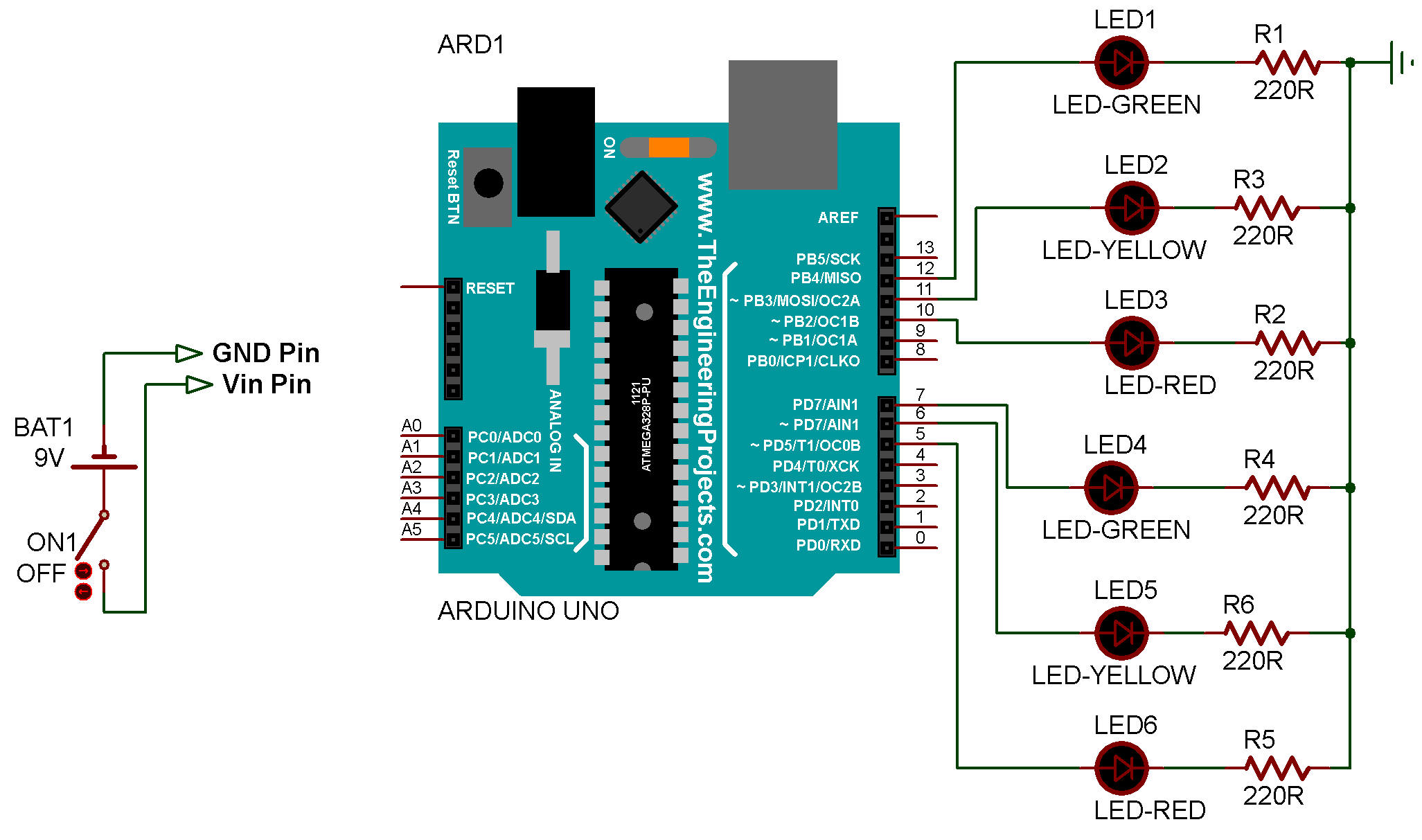
Step 2: Circuit Diagram: There is a total of 4 RGB LEDs used in this project. Each signal has 1 RGB led (Red, Blue and Green) connected to it through the 220-ohm resistors. Using the colour combination I have made a yellow colour for the signal. The resistors are used to limit the current that is going to pass through the LEDs.
Traffic Light 4 Way Using Arduino Uno Arduino Traffic Light Traffic Images
How to make Traffic Light Control System using Arduino | Arduino based 4 Way Traffic Signal ControlCode, Schematics and Proteus Simulation Download link:- ht.

4way traffic Lights using Arduino YouTube
ninar_araz October 8, 2021, 7:54pm 1. I'm having trouble by using millis for my 4 way traffic project, I have searched for a week and I can't seem to find a way and needless to say I didn't find any 4 way traffic light made with millis. I want to use millis because I want to display the countdown for the junctions on an lcd too.

DIY Arduino Traffic Light Pedestrian Light Push Button Control
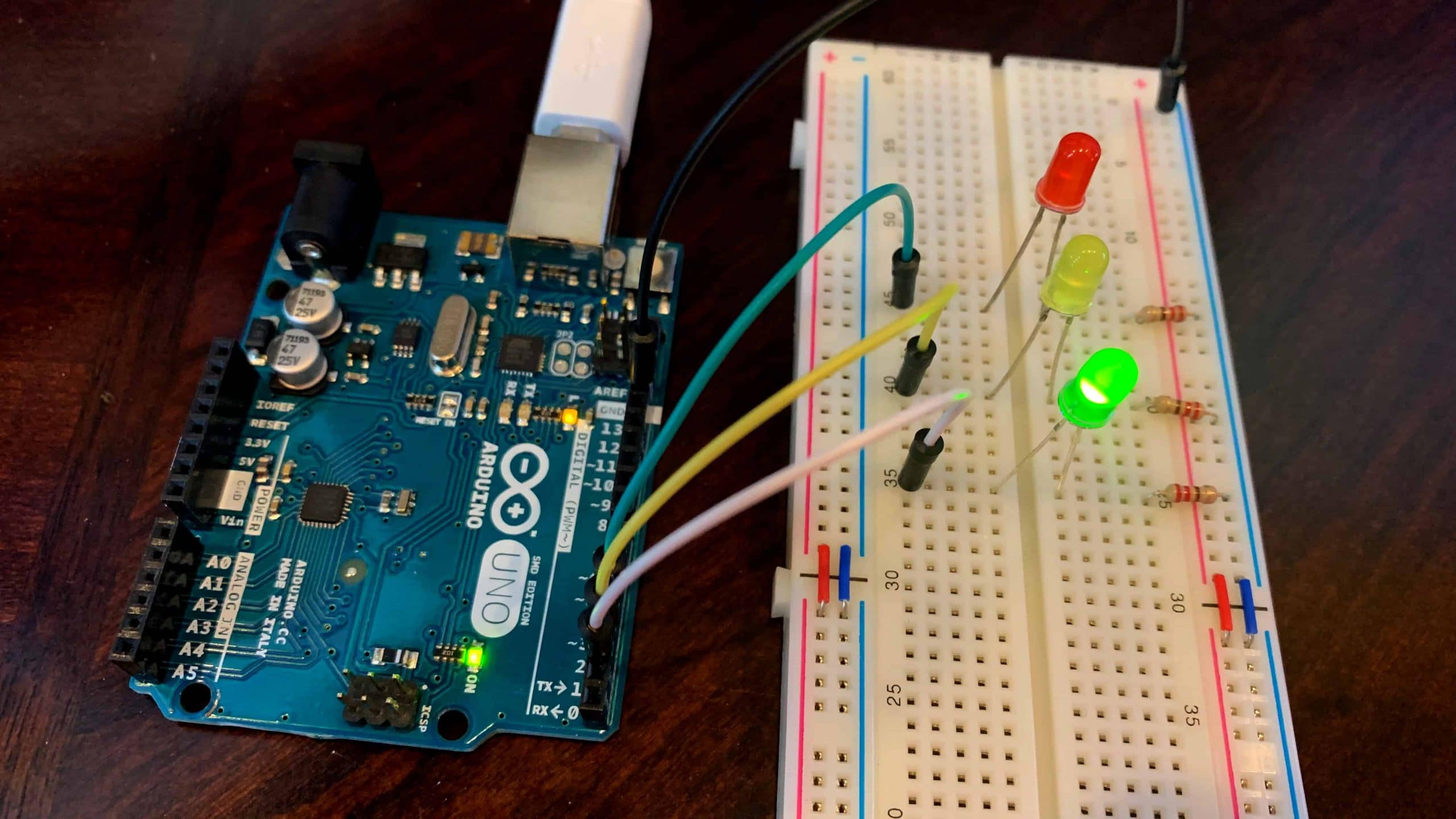
Arduino Traffic Light Circuit. The circuit that we need to set up is really simple and shouldn't take you too long to do. It's a fairly simple setup with each pin controlling an LED. Pin 2 goes to the positive leg of the green LED. Pin 3 Goes to the positive leg of the yellow LED. Pin 4 goes to the positive leg of the red LED.
Gallery Traffic Lights for Arduino Finite State Machine Hackaday.io
Components Required for Arduino Traffic Light Controller. The components you will be required for Arduino traffic light controller are as follows. Arduino Mega 2560. Red LEDs (4 pieces) Yellow LEDs (4 pieces) Green LEDs (4 pieces) 220 ohm resistors (12 pieces) Jumper cables. Breadboards.

Arduino based 4 Way Traffic Signal Control Arduino Project Hub
What You Need to Build an Arduino Traffic Light Controller. Apart from the basic Arduino, you'll need: 1 x 10k-ohm resistor. 1 x pushbutton switch. 6 x 220-ohm resistors. A breadboard. Connecting wires. Red, yellow and green LEDs. Almost any Arduino will work for this project, providing it has enough pins.
Arduino Traffic Light Project The Geek Pub
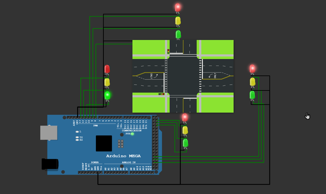
In this project, we are going to make a traffic light control for a four-way intersection. We will learn about traffic lights and how they work through an electronic project.. Code for the Arduino Traffic Light . 1-Assign the traffic lights pins to variables . int d_red =10; int d_yellow =9; int d_green =8; int r_red =4; int r_yellow =3; int.

Arduino Uno Traffic Light Hackster.io
Let's start small. A basic, single traffic light is a good place to start. Arduino Traffic Light. Let's start small. A basic, single traffic light is a good place to start.. Arduino Traffic Light Project Code. 1 int red = 10; 2 int yellow = 9; 3 int green = 8; 4 void setup.

How to Make Traffic Lights Using Arduino Uno Make Traffic Control System
A 4-way-Traffic-Light-Prototype-with-Arduino. This project aims at mimicking the process of controlling a 4-way Traffic light system using a Programmable Logical Controller. The project provides a virtual environment for testing, as well as a miniature physical environment to show the output of the earlier conducted simulation in real time.

Circuit design 4 Way Traffic Control Light System using Arduino in TinkerCad YouTube
Step 4: Wiring for 74HC595, 7-Segment Display and Nano. First, insert the 74HC595, 7-segment display and SunFounder Nano to the breadboard, then we connect them as shown in the table. Note: Connect the GND pin of the 7-segment display to a 220Ω resistor before grounding.
4 way Traffic signal project Arduino simulator projects Arduino Maker Pro
Hi there, I am currently working on a project seeking to recreate a 4-way traffic intersection with pedestrian crossings. So far I have the lights set up to change following the UK light pattern without using delays. I am designing this with the assumption that cars will only move straight across the intersection. Pedestrians will have a button to either cross vertically or horizontally on.

AdvRoboticsProject2 Arduino 4 way traffic light YouTube
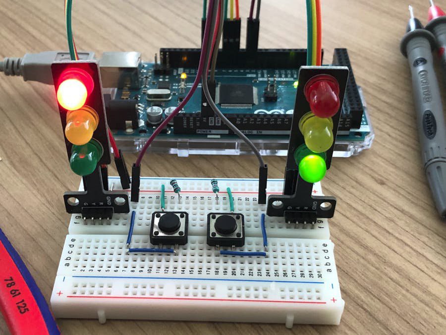
The main components of a 4-way traffic light are: Arduino Mega: For this circuit, we recommend using Arduino mega, that is because to control 4-way traffic along with pedestrian lights, we need 20 output pins while an Arduino UNO only has 14 digital I/O pins. Traffic light module: This is an inbuilt traffic light module you can find in Proteus.

Traffic Lights (4 ways) Arduino Project YouTube
A traffic light module includes 4 pins: GND pin: The ground pin, connect this pin to GND of Arduino. R pin: The pin to control the red light, connect this pin to a digital output of Arduino. Y pin: The pin to control the yellow light, connect this pin to a digital output of Arduino. G pin: The pin to control the green light, connect this pin to.