HVAC Plans Solution
The HVAC plans are schematic, using symbols and abbreviations to denote the various parts such as equipment, ducts, control devices, diffusers, and piping. For example, chilled water and hot water supply lines are denoted as: CWS - Chilled Water Supply CWR - Chilled Water Return HWS - Hot Water Supply HWR - Hot Water Return
Air Duct Cleaning Diagram of Your Home's HVAC System
Main Components of an HVAC System Diagram 1. Outdoor Unit (Condenser) These are the big boxes you see outside residential homes, business complexes, or on top of factory buildings. These boxes are one component of the HVAC system that works to cool your space.
Coleman Evcon Air Conditioner Not Working Sante Blog
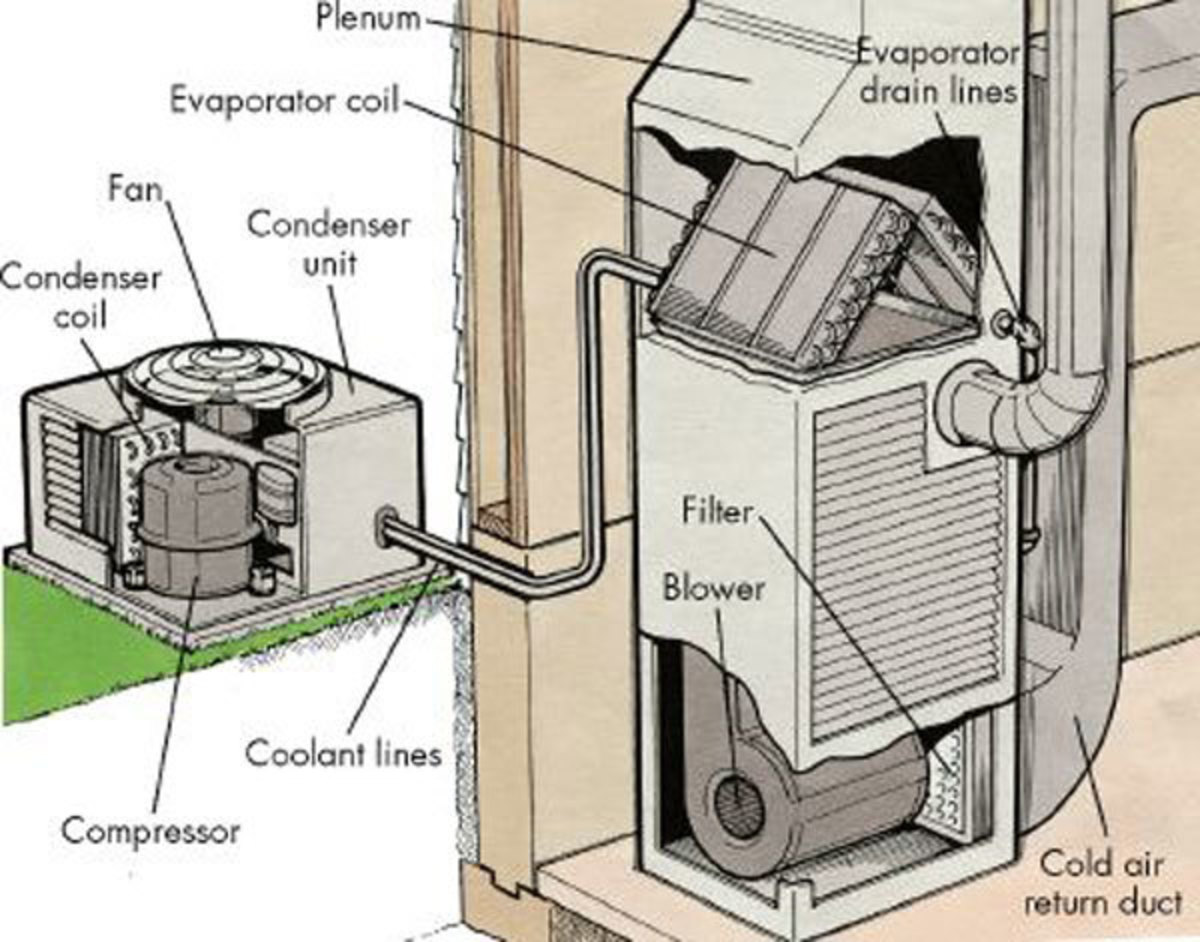
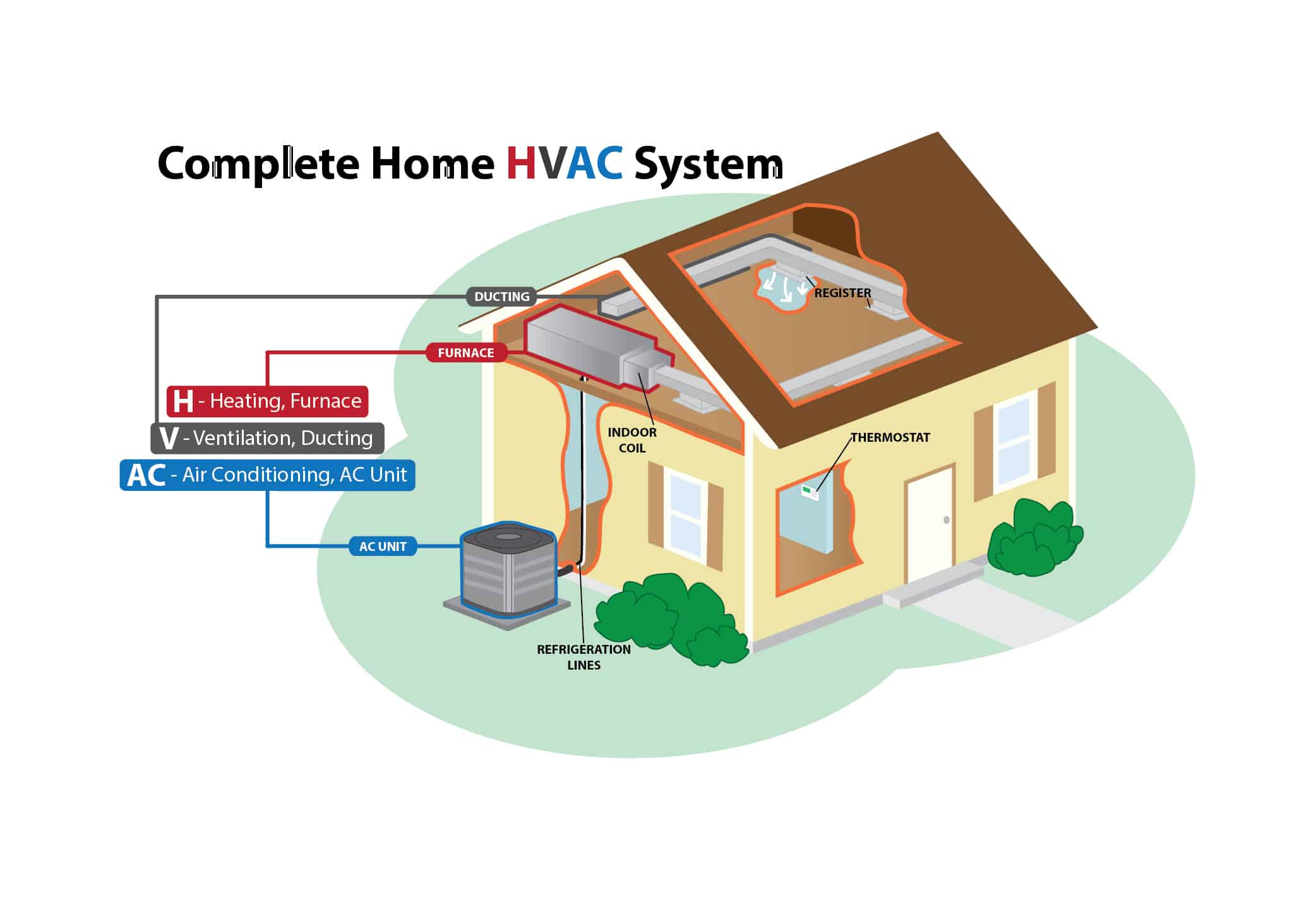
EVAPORATOR COIL. This is the piece of your air conditioning system that most people never see. It's contained in a metal box called a plenum, and sits on top of your furnace. If you have a horizontal furnace in an attic, the evaporator coil will sit on one end of the furnace instead of on top. The 'inside unit' or 'indoor coil' are.

Introduction to HVAC System
Are you looking to improve the efficiency of your heating, ventilation, and air conditioning (HVAC) system? The key to achieving optimal efficiency lies in designing a well-planned HVAC system that considers your space's unique needs and characteristics. Apartment HVAC Plan

Basic Principles of a HVAC system ENGINEERING UPDATES
HVAC is a term stemmed from 'Heating, Ventilating, and Air Conditioning', and it is a system that is aimed to provide comfort for indoor areas. Science contributes to identification of various measures for that comfort and thermal control, and HVAC systems will be engineered based on the desired design points.
/cdn.vox-cdn.com/uploads/chorus_asset/file/19521285/air_handler.jpg)
Diagram Of Residential Hvac System Hvac Manuals Wiring Diagrams Faqs
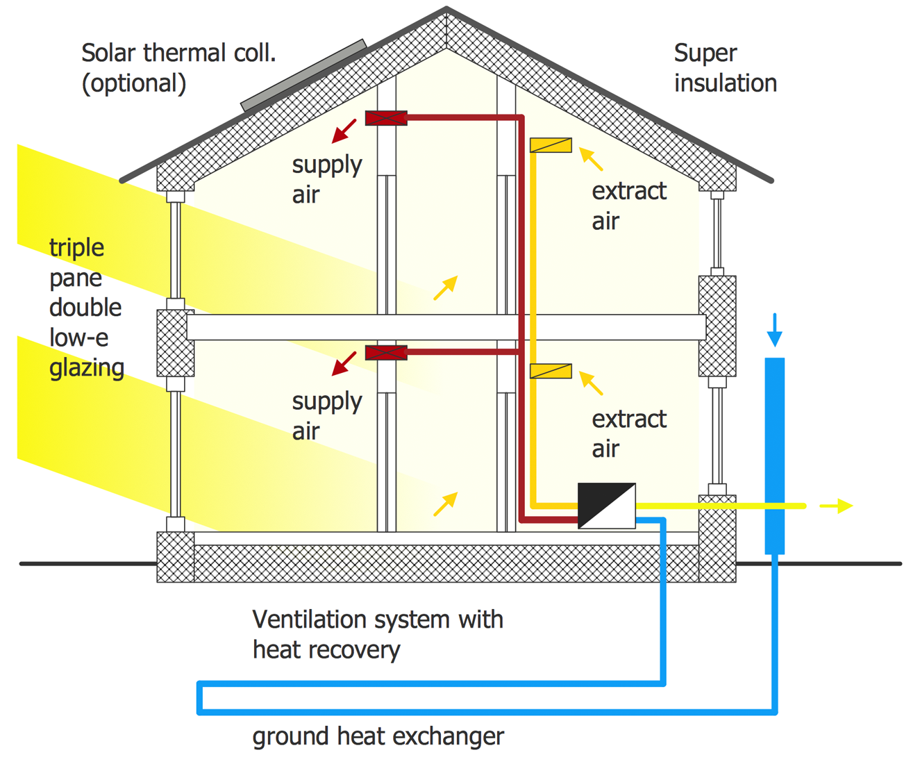
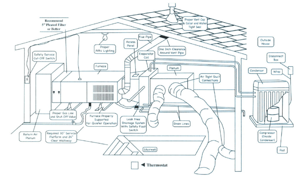
By Scott Gibson | May 8, 2020 Long before an HVAC system can be put to paper a variety of calculations must be made about heating and cooling demands, how conditioned air will be circulated, and what type of equipment is most appropriate for both the house and the climate. Drawing courtesy PAE Consulting Engineers.
:max_bytes(150000):strip_icc()/what-are-central-air-conditioners-1152645_V2-390c6f1f6ca14b4ebc59426f226a78a8.png)
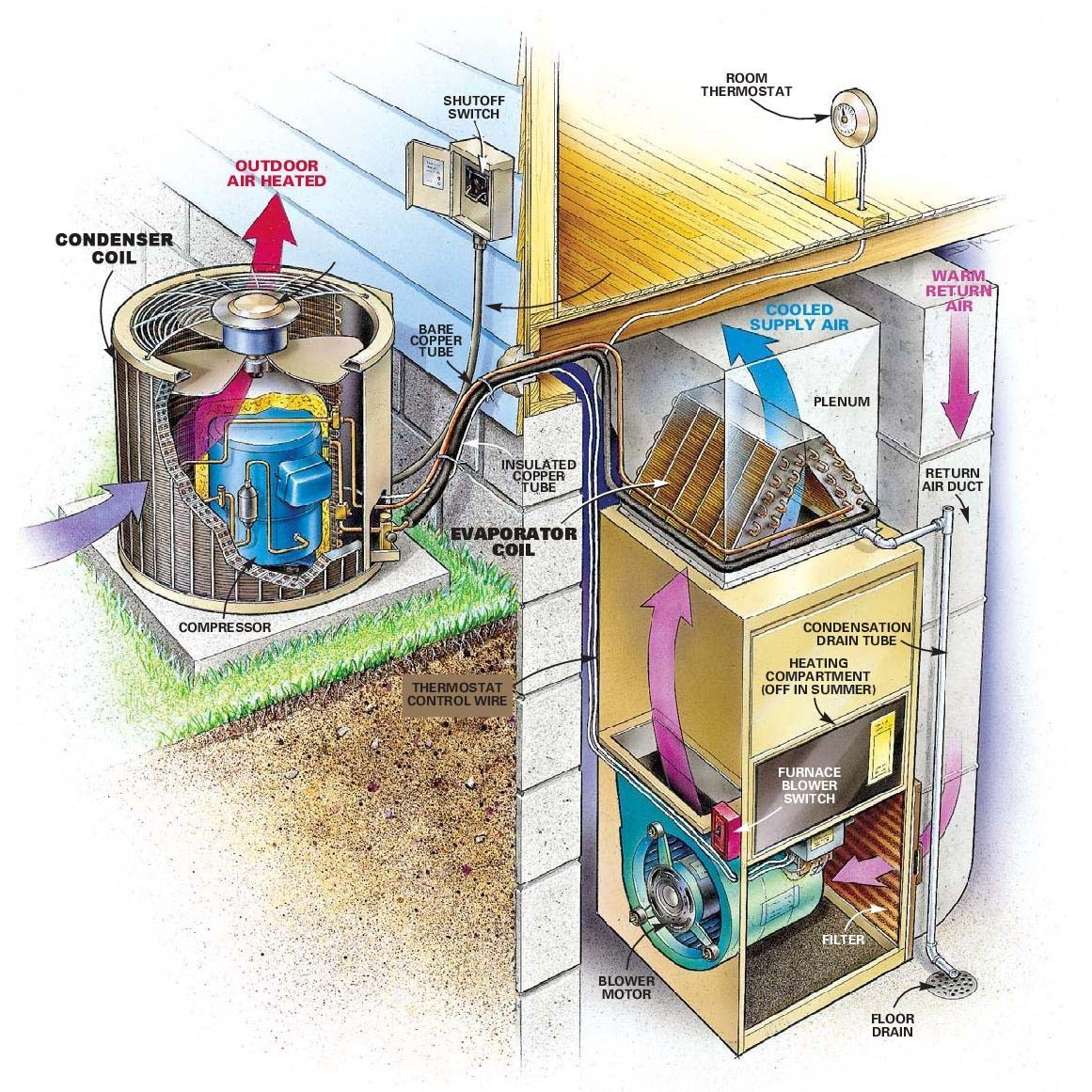
How a Central Air Conditioner Works
In conclusion, unravelling the complexities of HVAC systems through the lens of a comprehensive diagram empowers homeowners and professionals alike. A nuanced understanding of the system's anatomy enables informed decisions, ensuring both comfort and efficiency. hvac system diagram In the realm of indoor comfort, HVAC systems play a pivotal role.

hvac diagram for a building Google Search Building Summary
HVAC system diagrams and schematics fall into three different categories: ladder, line, and installation diagrams. Here's how those break down. Ladder Diagrams.
Hvac Systems new Residential Hvac System
Schematic diagrams work as a guiding aid for technicians, helping them to locate components and detect malfunctions quickly. This makes the repair or replacement process error-free and fast. Schematic diagrams also show the electric connections of the system. It is important for technicians and engineers to know these well so that they can.

This simple diagram shows you how your HVAC system's ductwork connects
HVAC Definition. HVAC is an acronym for heating, ventilation, and air conditioning. HVAC systems control the temperature inside the home through a variety of methods, though most involve pumping air over cooling coils or a heat exchanger to increase or decrease the air temperature. The air is then blown into the home through vents and ductwork.

What is HVAC? How does it work? HVAC basics
HVAC System Installation Diagram Common HVAC Problems and Solutions Diagram HVAC Safety Considerations Conclusion: Recap and Final Thoughts on Home HVAC Diagrams HVAC Basics What Does HVAC Stand For? First things first, let's decode that HVAC acronym. HVAC stands for Heating, Ventilation, and Air Conditioning.

Household Disasters Head off These Home Problems Early or Pay the
HVAC System Diagram: Everything You Need To Know August 12, 2020 | Gee! Heating & Air | Air Conditioning, Heating, HVAC When the mercury begins to rise and sweat beads form on your forehead, nothing feels better than sitting in your air-conditioned home.

hvac duct system design Google Search Hvac design, Hvac, Hvac duct
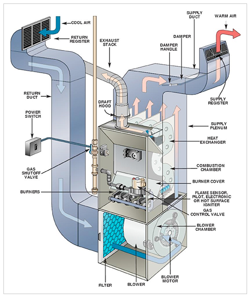
1.Burning propane or natural gas generates heat in the furnace's burner. 2.The heat produced passes through a heat exchanger, making it hot. 3.Air from the home's ductwork is blown over the heat exchanger, warming the air. 4.The furnace's blower then forces the heated air into the supply ductwork, distributing it throughout the home.
Install Central Air Cost Great Discounts, Save 49 jlcatj.gob.mx
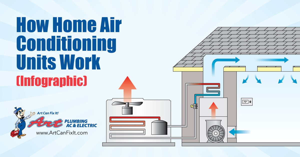
The compressor pressurizes the refrigerant gas and sends the refrigerant into the outdoor unit's condenser coil. A large fan pulls outdoor air through the condenser coil, allowing the air to absorb heating energy from the home and release it outside. During this process, the refrigerant is converted back to a liquid.
How Hvac Systems Work Diagram
Bob Formisano Updated on 07/28/19 Nine OK / Getty Images The workings of a home air-conditioning system are mystifying to many of us. Furnaces are easy to understand—they heat air and blow it around your home through ductwork. Boilers make hot water or steam and move it around your home in pipes.
Furnace System Diagram Main Parts Of A Furnace With Diagram Upgraded
The HVAC system consists of 5 key components that are all shown in the diagram above: Compressor - The compressor is the machine inside the air conditioning box outside of your home. It is used to compress refrigerant which simultaneously heats it before the refrigerant goes into the condenser.