Sheet Metal Drawings For Practice Pdf Aesthetic Drawing
Lesson 1 Introduction WelcometoselfpacedtrainingforSolidEdge.Thiscourseisdesignedtoeducateyou intheuseofSolidEdge.Thecourseisself-pacedandcontainsinstructionfollowed

sheet metal drawings for practice pdf Alyse Britton
For a slot or hole > 1" diameter then the minimum distance "D" = 2.5T + R (see fig. "C") Form height to thickness ratio - To determine the minimum form height for sheet metal use the following formula: D = 2.5T + R (see below) The height can be less but it required secondary operations and is far more costly.

sheet metal drawings for practice Jeffrey Cherry
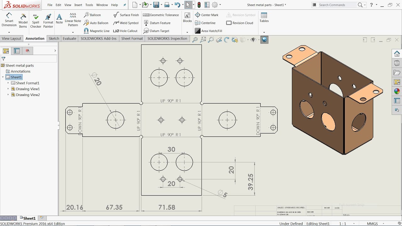
Exercise 2. Drawing of Rim Figure 49 Wheel Assembly Exercise 3. Drawing of Shaft Figure 50 Annotations Exercise 4. Drawing of Sheet metal part Figure 51 Sheet metal Exercise 5. Drawing of Sheet metal part Figure 52 Multibody sheet metal TOPICS: Drawings Tools View Palette Model View Section View Section View Assist

Sheet Metal Drawings For Practice Pdf Warehouse of Ideas
Experimental Analysis for Defining Forming Limit Diagram for Thick Sheets. Atanas Kochov. In this paper a combined procedure to determine the forming limit diagram (Keeler-Goodwin diagram) for thick sheets is proposed. It is defined for cold rolled steel sheet Č0147 (RSt 13 DIN 17006) with thickness of 5 mm using two different criteria.

sheet metal drawings for practice Much Indeed Forum Image Archive
5 • Blend Create a sheet metal wall by blending several sections sketched in parallel planes as shown in Figure SM.10. Figure SM.10 Base Feature, Blended Wall • Flat Sketch the boundaries of the wall (Fig. SM.11). Figure SM.11 Feature, Flat Wall • Offset Create a wall that is offset from a surface (Fig. SM.12). Figure SM.12 Base Feature, Offset Wall.

Percepire prova Antologia sheet metal drawings mantenere aggrovigliamento Treno
This chapter explains how to create sheet metal drawings. Gauges for sheet metal are presented along with bend radii, flanges, tabs, reliefs, and flat patterns. Sheet Metal Drawings Figure 13-1 shows a 3D solid model of a sheet metal part and a dimensioned orthographic drawing of that part. The orthographic drawing was created from the 3D model.

Sheet Metal Practice Drawing Sheet metal drawing, Drawing practice, Mechanical design
Do you want to practice your sheet metal skills in SOLIDWORKS and prepare for the CSWPA-SM exam? Download this free sample exam and test your knowledge of sheet metal design, modeling, and drawing. You will find detailed instructions, questions, and solutions for each part of the exam.
sheet metal drawings for practice pdf photographyascontemporaryart
Extracting Drawings from the Sheet Metal Part All together, these tasks should take about 15 minutes to complete. This tutorial, which is common to the Sheet Metal Design User's Guide and to the Generative Sheet Metal Design User's Guide, is illustrated using screen captures from the Sheet Metal Design workbench.

Sheet Metal Drawings For Practice Pdf Warehouse of Ideas
How to take this sample exam: The questions in this sample exam give an indication of the type and difficulty of the questions on the real exam but ARE NOT MEANT TO REVEAL ALL THAT IS COVERED ON THE TEST. For a list of topics covered on the CSWP-SMTL exam, please go to www.solidworks.com/cswp.

sheet metal drawings for practice pdf lineartdrawingsaestheticbutterfly
Drawings of Sheet Metal Parts. When you create a drawing of your sheet metal part, a flat pattern is automatically created. Drawings of sheet metal parts can also contain views of the bent sheet metal part. You can create *.dxf files of sheet metal flat patterns without creating a drawing.

3D MODELING PRACTICE 698 STUDY CADCAM Mechanical Engineering Design, Mechanical Design
drawings and Manufacturing. Remember to do all design work in the bent state or generic, so your model will be correct. 8. Create drawing, showing bent and flat states on the same page. Show the dimensions on the bent part, create ordinate dimensions on the flat state. Sheetmetal Pocket Demo Page 3 of 5

sheet metal drawings for practice Jeffrey Cherry
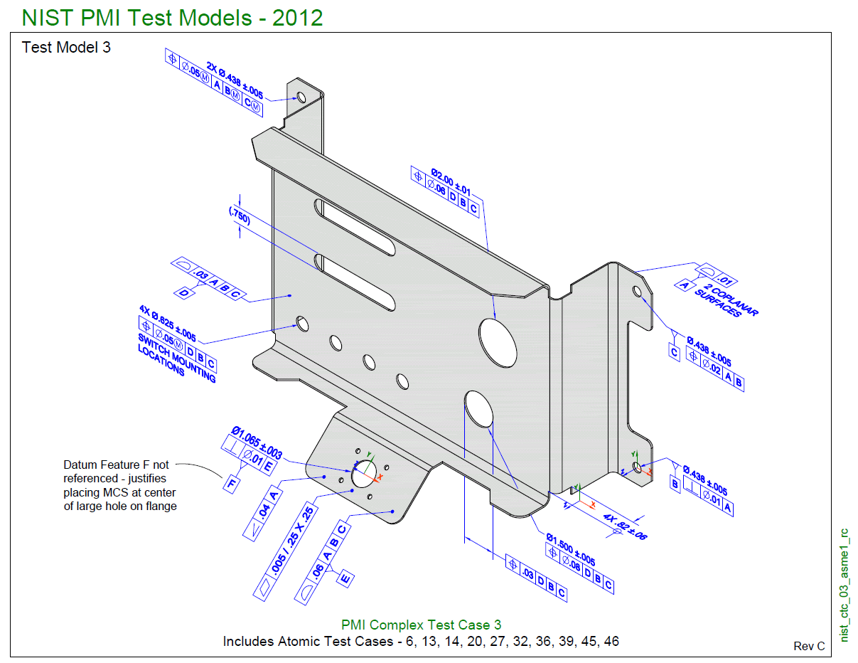
A fully dimensioned sheet metal drawing includes dimensions for all bends, holes, countersinks, flanges, and other formed features (such as hems and curls, ribs, dimples, etc…). It is a best practice to dimension to virtual intersection points and show included bend angles. This ensures that your drawing is universally interpret-able (with no.

i want sheet metal part drawings to practice iam not able to get from google can anyone pls help
Summary: In this exercise, you'll create a sheet metal bracket. You'll use a combination of different flange features to create the base and utilize sheet metal features to finish the part. Reference Lessons: Sheet Metal and Flat Pattern Features Base Flange Edge Flange Break Corner Sheet Metal Gussets Instructions:
Share more than 67 sheet metal drawings for practice latest nhadathoangha.vn
Contents Acknowledgements Safety First Introduction 1 Materials 2 Drawing and Developing Stages 3 Measuring and Marking Out 4 Cutting Sheet Metal 5 Making Holes 6 Bending Sheet Metal 7 Rolling, Beading, Flanging and Wiring 8 Joining 9 Forming, Pressing and Drawing 10 Surface Finishing Projects: 1 Fuel Tank for a Model Aircraft 2 Motorcycle Ammet.

sheet metal drawings for practice pdf lineartdrawingsaestheticbutterfly
The purpose of this GoProto Sheet Metal Design Guide is to help you de ne the speci cs so that your designs are ready to go in production with us in such a way that theoretical versus actual is minimal and your features match available processes. This will help us make your parts fast, make them right and make them inexpensively.

Sheet metal drawings for practice Mechanical Engineering GrabCAD Groups
Now let's use SolidWorks to create a sheet metal transition. 27. Start a new inch part and create a new Sketch on the front plane. Constrain the geometry and dimension as shown. The rectangular geometry on the right side of the sketch is used to create and center a gap in the sketch geometry.