Anstrengung Scharf Notfall ads1115 arduino library sprechen Rachen Weinen
This Arduino I2C tutorial explains the I2C pins in Arduino, configure Master and Slave and finally a simple demonstration in which two Arduino UNO board communicates over I2C. Outline Toggle What is I2C? I2C Bus I2C in Arduino How to use Arduino I2C Interface? Components Required Circuit Diagram Code Wire Library
i2c ads1115 16 bit adc 4 channel module with programmable gain amplifier for arduino rpi Sale
The communication between the module and the Arduino board is done by the I2C protocol. Tip: The built-in 10-bit ADC of Arduino has a lower accuracy compared to the ADS1110 module. Therefore, to measure the analog data more accurately (such as a sensor or module output or the voltage difference between two points), we recommend using the ADS1110 module.

TZT 16 Bit I2C ADS1115 Module ADC 4 channel with Pro Gain Amplifier for Arduino RPiamplifier
Initialize the ADC for operation using the default address and I2C bus. begin (0x49); Initialize the ADC for operation using specified address of 0x49. Example: The following examples assume an ADS1015 and use a 3 mV/bit scaling factor. For the higher-resolution ADS1115, the scaling factor would be 188uV/bit. Download File Copy Code

ADS1015 12Bit ADC 4 Channel with Programmable Gain Amplifier For microcontrollers without
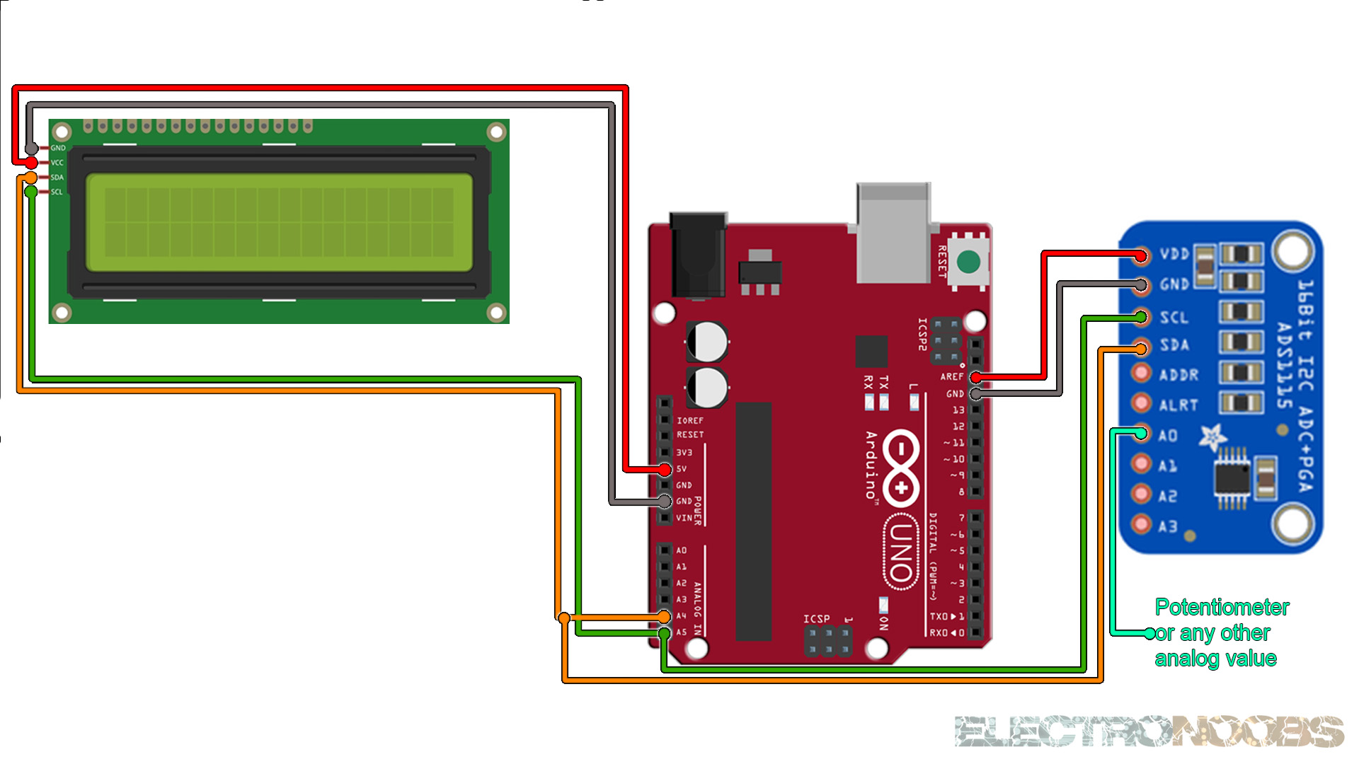
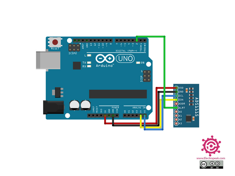
Here's how we will connect the boards. The Serial Clock pin of the Arduino Board will be connected to the Serial Clock pins of the two breakout boards, the same goes for the Serial Data pins and we will power the boards with the Gnd and the 5V pin from the Arduino Board. Note here we are not using pull-up resistors because the breakout boards.
16 Bit I2c Ads1115 Module Adc 4 Channel With Pro Gain Amplifier For Arduino Rpi 1pcs
ADS1115 I2C external ADC with ESP32 in Arduino IDE This guide will assist you in interfacing the external ADC module AD1115 with ESP32. This is done to measure analog voltages with high accuracy. The ADS1115 external ADC module can send data over the I2C protocol.
ADC121C021 1Channel 12Bit HighSpeed ADC with I2C Interface
The I2C protocol is supported on all Arduino boards. It allows you to connect several peripheral devices, such as sensors, displays, motor drivers, and so on, with only a few wires. Giving you lots of flexibility and speeding up your prototyping, without an abundancy of wires.

DFR0553 Dfrobot I2C ADS1115 16Bit ADC Module, for Arduino and Raspberry Pi Board
#include
Anstrengung Scharf Notfall ads1115 arduino library sprechen Rachen Weinen
This code reads voltage values from four analog input pins (A0-A3) on an ADS1115 analog-to-digital converter (ADC). The ADC is connected to an Arduino using the I2C protocol. In the void setup function, the ADC is initialized, and its mode is set to single-shot sampling, which means it will perform a single conversion when triggered. The ADC.
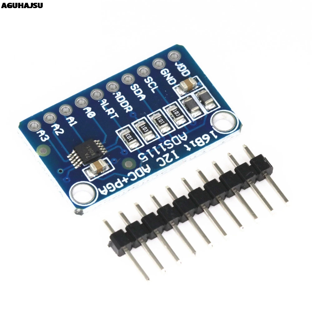
ADS1115 I2C 16Bit ADC Module
The Arduino outputs I2C signals at a 5V logic level. But I2C devices can operate at a range of different logic level voltages. An I2C device that operates at 3.3V could be damaged if connected to the Arduino. The device's datasheet should tell you it's logic level voltage.
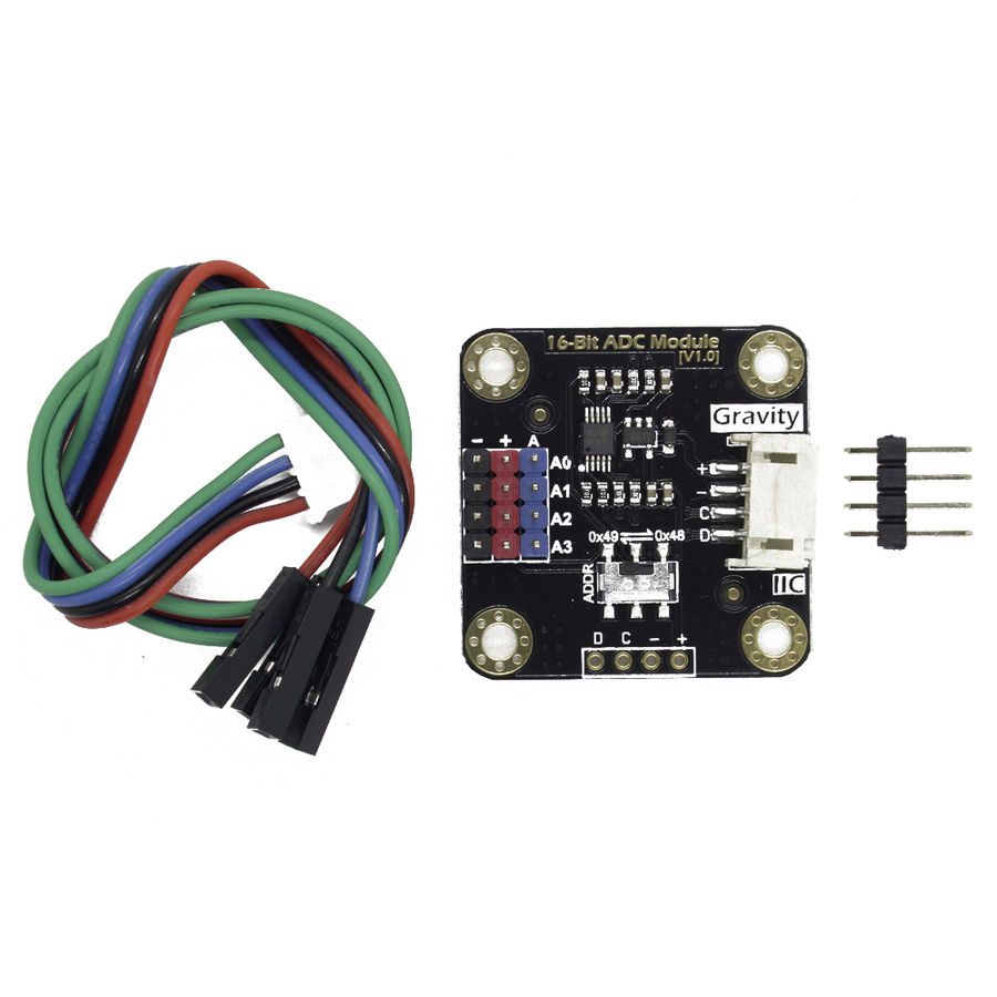
Buy I2C ADS1115 16Bit ADC Module (Arduino and Raspberry Pi Compatible) with Gravity Affordable
The Arduino built-in Wire.h library for I2C communication enables the internal pullup resistors for both SDA & SCL lines. The internal pullup resistors (Rpu= 20~50kΩ) are pretty much weak and not sufficient. Therefore, you can manually disable them in code, and connect your external I2C pullup resistors.
ADS1115 ADC 4 Channel 16Bit I2C PGA Low Power Arduino Raspberry Pi 2 ESP8266 PIC eBay
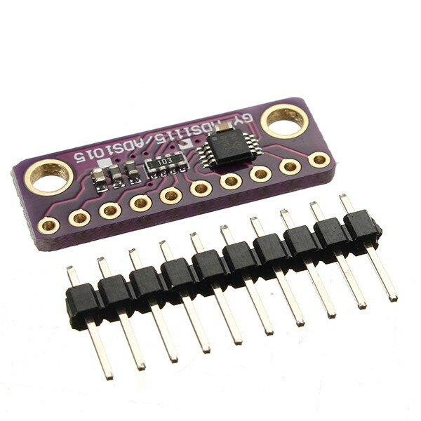
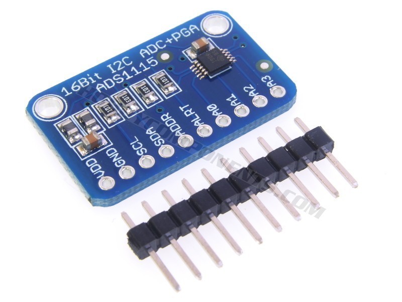
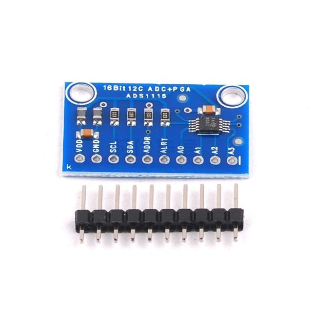
Step 1: Circuit Step 2: Installing Library Step 3: Code ADS1115 16-Bit ADC Module Features Almost all microcontrollers come with ADC pins, but they lack high precision.
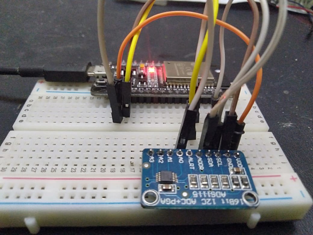
ADS1115 I2C external ADC with ESP32 in Arduino IDE
Arduino has internal ADCs that we use when we use the Arduino analog inputs. On the Arduino Uno, Mini and Nano models, we have 6 ADC of 10 bits. The ADS1115 provides 4 16-bit ADCs, 15 for the measurement and one last for the sign. The ADS1115 is connected by I2C, so it is easy to read. It has 4 addresses, which is chosen by connecting the.
ARDUINO
Using Python and I2C to Read the ADC Pin. Instead of using a write_byte() method to write to the I2C bus, we use a read_byte() one to read from it. This method takes the I2C address as an argument and returns the value it reads. Try it: i2cbus.read_byte(arduino) Turn the potentiometer to change the voltage on the pin and then run the command again.

ADS1115 ADC 16 bit high precision Arduino Tutorial
This library is compatible with all architectures so you should be able to use it on all the Arduino boards. Releases To use this library, open the Library Manager in the Arduino IDE and install it from there. 2.0.2 (latest) 2.0.1 2.0.0
Ads1115 Module 16 Bit I2c 4 Channel ADC With Pro Gain Amplifier for Arduino for sale online eBay
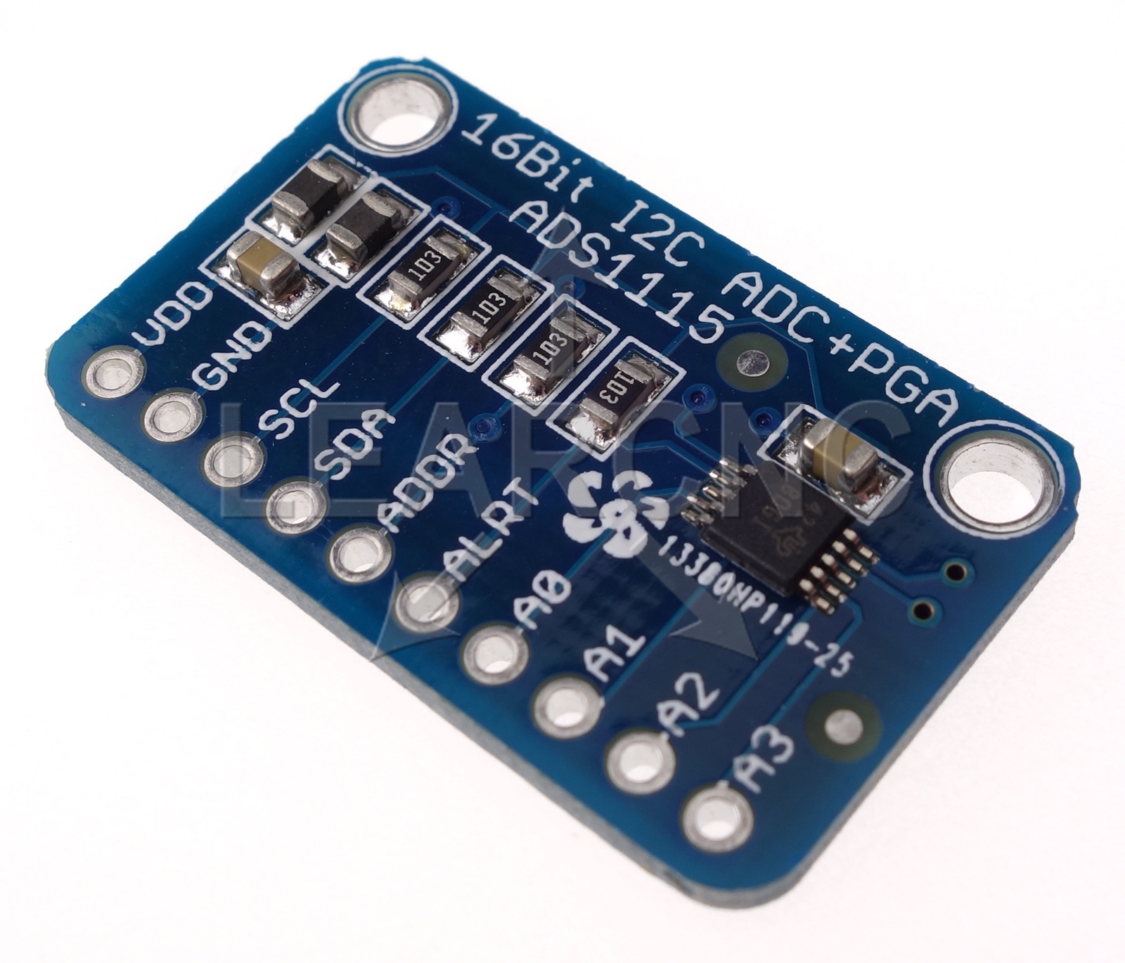
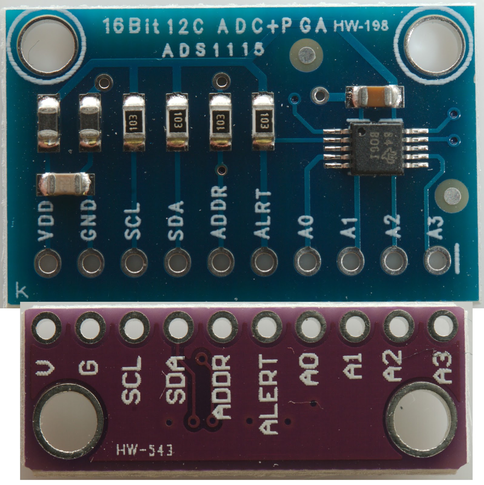
The ADS1113, ADS1114, and ADS1115 devices (ADS111x) are precision, low-power, 16-bit, I 2 C-compatible, analog-to-digital converters (ADCs) offered in an ultra-small, leadless, X2QFN-10 package, and a VSSOP-10 package. The ADS111x devices incorporate a low-drift voltage reference and an oscillator.

I2C 12Bit, 8CH AnalogtoDigital Converter
I2C (Inter-Integrated Circuit) is a communication protocol widely used in electronics and devices. It connects devices using two wires: one for data and one for a clock signal. One device or more can be designated to act as the "controller" and control communication, while the others are "peripherals."