
Air Compressor Wiring Diagram 230v 1 Phase Free Wiring Diagram
The air moves from the discharge port to the tank. With each stroke, more air enters the tank and the pressure rises. Typical compressors come in 1- or 2-cylinder versions to suit the requirements.

Air Compressor Wiring Diagram 230v 1 Phase Free Wiring Diagram
Parts of An Air Compressor Diagram Guide - Air Compressor Parts List Air Compressor Brands Identifying an Air Compressor Brand or Model Find Help By Air Compressor Make or Brand Need Info on a Brand of Compressor not Listed A-D Alltrade Air Compressors Alton Air Compressors Atlas Copco Air Compressors Bambi Air Compressors Belaire Air Compressors
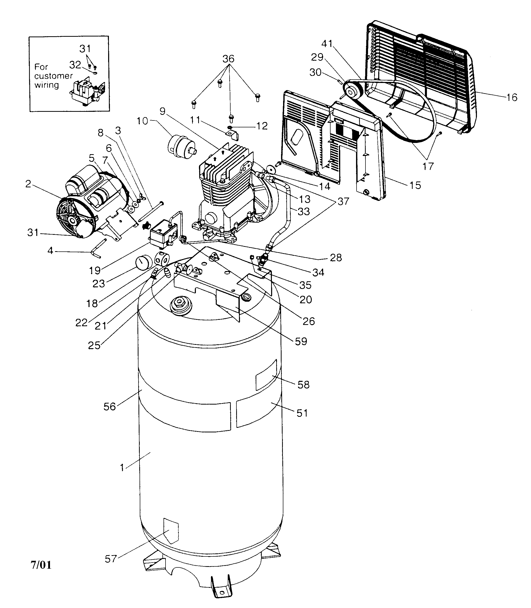
CRAFTSMAN AIR COMPRESSOR Parts Model 919184170 Sears PartsDirect
Air Compressor. To wire a 240V air compressor, connect the black and white conductors to the breaker and ensure there is no neutral wire needed. The remaining steps can be found in various YouTube videos and forums dedicated to air compressor wiring, providing detailed instructions and diagrams. These resources offer guidance on double-checking.

Air Compressors and Compressed Air Systems, Part Two
1.5.2 Positive displacement compressors 20 1.5.3 The compressor diagram for displacement compressors 20 1.5.4 Dynamic compressors 22 1.5.5 Compression in several stages 23 1.5.6 Comparison: turbocompressor and. 3.5.4 Intake air 85 3.5.5 Compressor room ventilation 86 3.6 COMPRESSED AIR DISTRIBUTION 89 3.6.1 General 89

Campbell Hausfeld HL5516 Parts Diagram for Parts
An air compressor is a machine that takes ambient air from the surroundings and discharges it at a higher pressure. It is an application of a gas compressor and a pneumatic device that converts mechanical power (from an electric motor, diesel or gasoline engine, etc.) into potential energy stored in compressed air, which has many uses.

Schematic drawing of the compressor test system. Schematic drawing of... Download Scientific
An air compressor, as the name indicates, is a machine to compresses the air and raises its pressure.The air compressor absorbs air from the atmosphere and compresses it. Then it sends to a storage vessel under high pressure. From the storage vessel, it can be carried by pipeline to a location where a supply of compressed air is needed.

I'm rebuilding an old air compressor. compressor is a 5 hp 15 cfm two stage. the motor is a
An air compressor diagram is a visual representation of an air compressor system, highlighting its components and their functions. This diagram serves various purposes and can be used in a variety of settings. In this section, we will discuss the different uses of an air compressor diagram, including troubleshooting and maintenance, designing.

Ingersoll Rand Air Compressor Wiring Diagram Free Wiring Diagram
Return to Resource Library. > Click to download Chapter 4 - Compressed Air System Design, 2021 - 7th Edition PDF.

Bendix Air Compressor Diagram
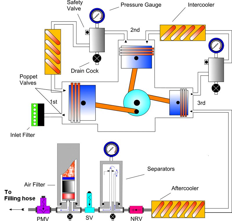
Double Acting Reciprocating Air Compressors. A schematic diagram of a typical double acting reciprocating air compressor is shown below. These are usually categorized under multi-stage reciprocating air compressors, but let us restrict the study to double acting/stage compressors concerned with the AE/JE mechanical engineering exams.
Compressors Scuba Engineer
The diagram of how an air compressor works consists of a motor which powers the compressor pump to move the air through the compressed air tank. In the compression chamber, the air is drawn through a suction valve and forced into a discharge valve, where the compressed air is released to power a wide range of tools and machinery.
Campbell Hausfeld FP209402 Parts Diagram for Parts
1. Rotary Screw Rotary screw compressors have two internal "screws" that rotate in opposite directions, trapping and compressing air between them.
Air Compressors Principles, Types and Functions Inspirational Technology
Air Compressor Piping Diagrams and Tips From Experts About Air Compressors.com Air Compressor Brands Identifying an Air Compressor Brand or Model Find Help By Air Compressor Make or Brand Need Info on a Brand of Compressor not Listed A-D Alltrade Air Compressors Alton Air Compressors Atlas Copco Air Compressors Bambi Air Compressors
Campbell Hausfeld MT5019 Parts Diagram for Parts
An air compressor flow diagram is a visual representation that illustrates the various components and processes involved in the operation of an air compressor system. It provides a comprehensive overview of how air compressors function and how they generate compressed air for various applications.
Campbell Hausfeld FL3501 Parts Diagram for Parts
Now let's discuss the actual operation of an air compressor with indicator diagrams. Operation: To understand the operation of an air compressor, let us assume the cycle and indicator diagram for a simple single stage reciprocating air compressor, as shown below. (Click the image to enlarge.)

Craftsman Air Compressor Capacitor Wiring Diagram
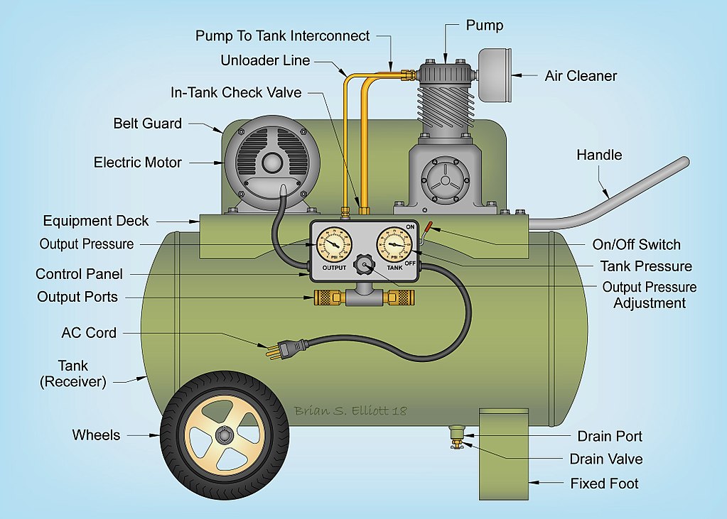
Fluid-Aire Dynamics Blog What Are the Parts of an Air Compressor: Diagram of Air Compressor Parts Table of content Air Compressor Working Principles Core Elements of the Air Compressor Other Common Air Compressor Parts Reciprocating Air Compressor Parts Diagram Rotary Screw Air Compressor Parts Diagram Need Air Compressor Parts?

Campbell Hausfeld HL4215 Parts Diagram for Parts (2009)
Updated: May 16, 2022 We may earn commission from our brand partners when purchasing products through our links. Learn more. You have created your own air compressor piping diagram when you attach a compressor to an end-user device through a pipe.