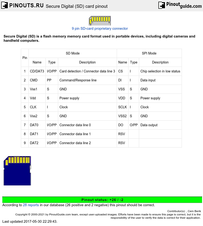
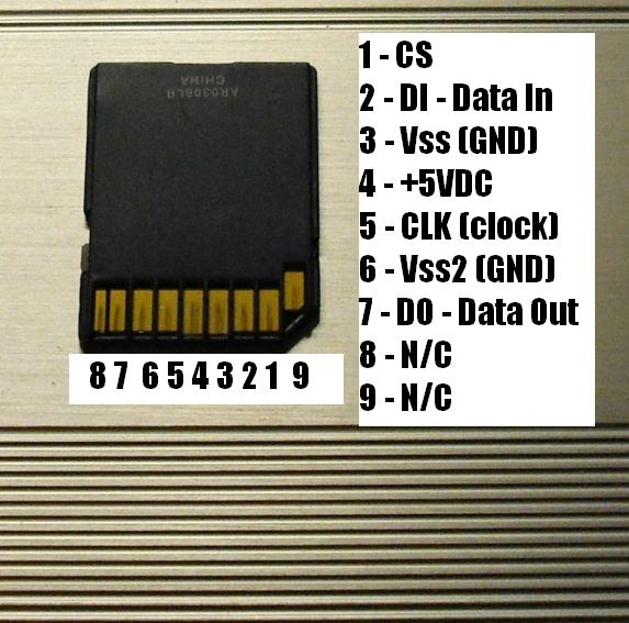
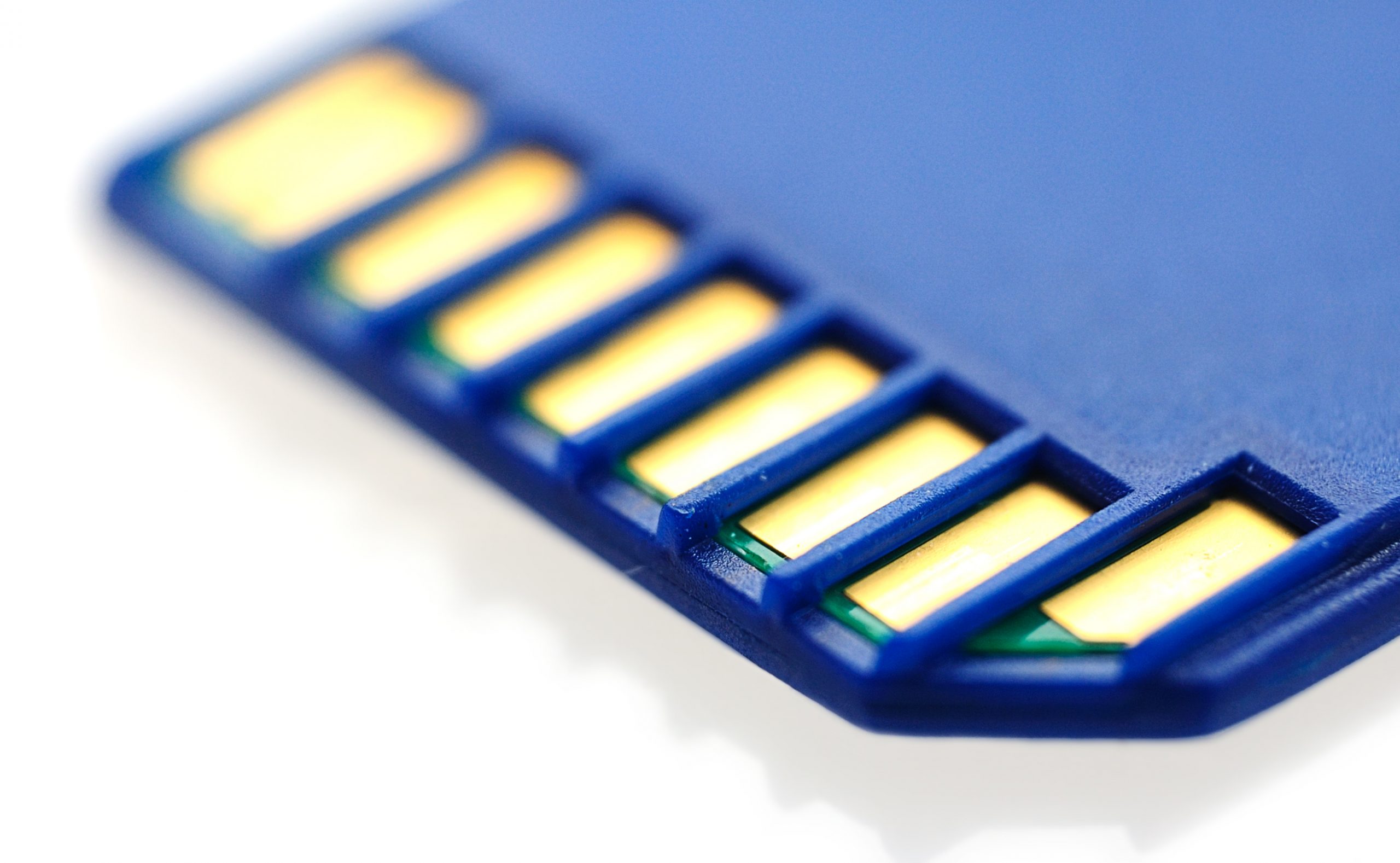
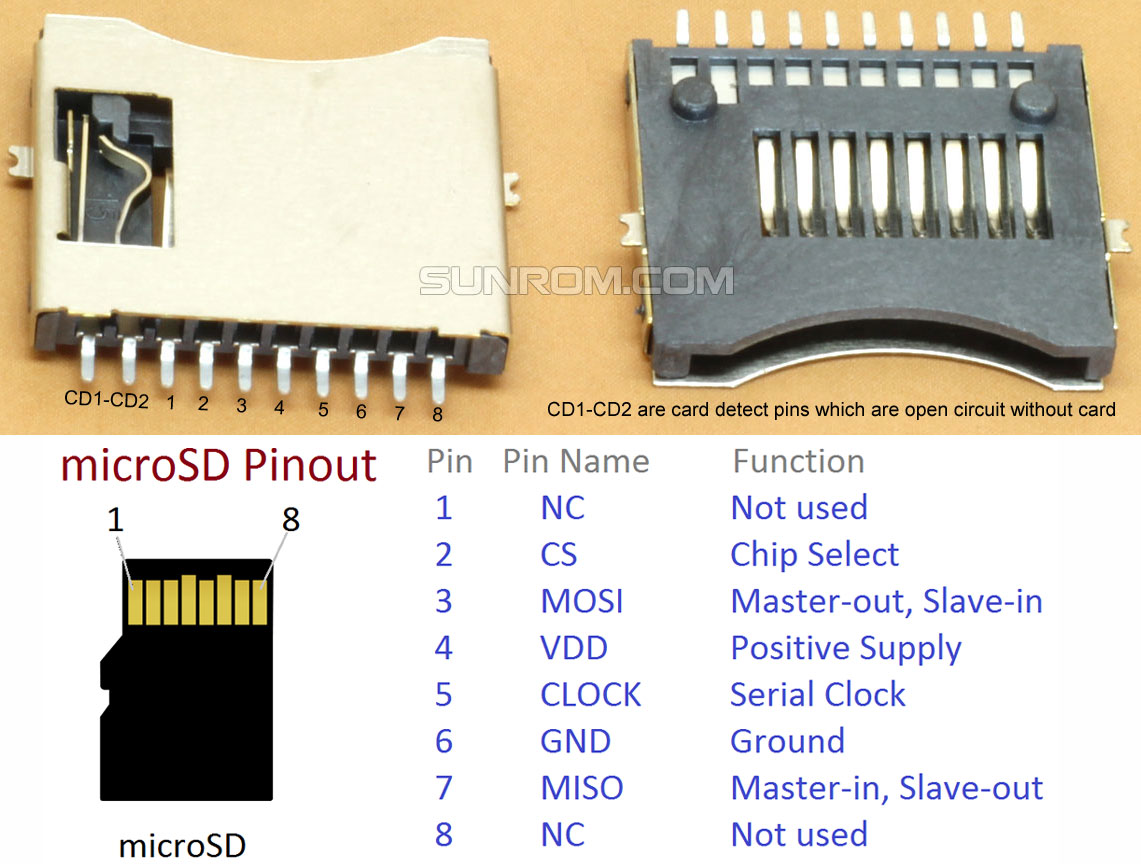
Secure Digital (SD) card pinout diagram
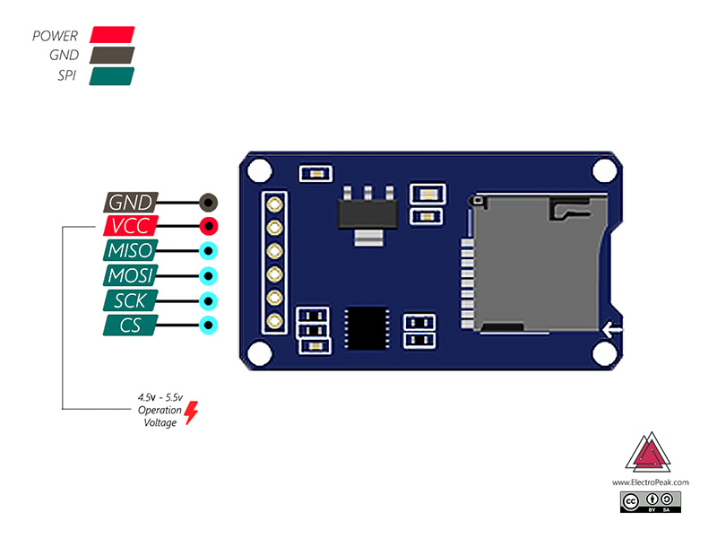
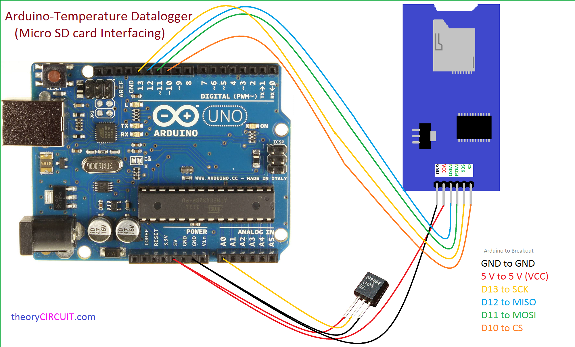
Connect the 5 V pin on the Arduino to this pin. 5 V is the input supply for the SD card module. CS: Chip select pin. This pin is the output pin of the Arduino and the input pin for the SD card module. MOSI: Master Out Slave In Pin. This pin is the output pin of the Arduino and the input pin for the SD card module. SCK: SPI Clock line.
MicroSD Pinout A Stepbystep Guide
Quick Steps. Insert the Micro SD Card to the Micro SD Card module. Do the wiring between the Micro SD Card module and Arduino as the above wiring diagram. Connect Arduino to PC via USB cable. Open Arduino IDE, select the right board and port. Open Serial On Arduino IDE.
SD Card Pinout Basics Delkin Devices Rugged Controlled Storage
CD (not sure what it stands for, but this pin isn't used when connecting to an Arduino. I think it's used for faster transfers.) Note that SD card run at 3.3Volt, not 5V. Also the input pins of the SD can't handle 5Volt signals. So you need to convert the 5V signals coming out of the UNO to 3.3V before connecting to the SD card.
Memory card SD card parts , types , pin , sd card speed YouTube
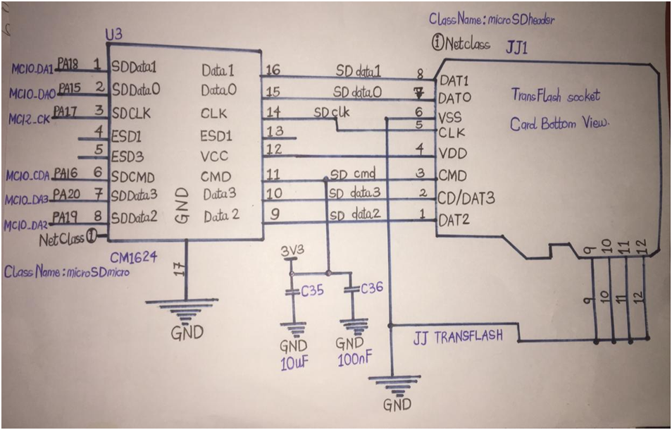
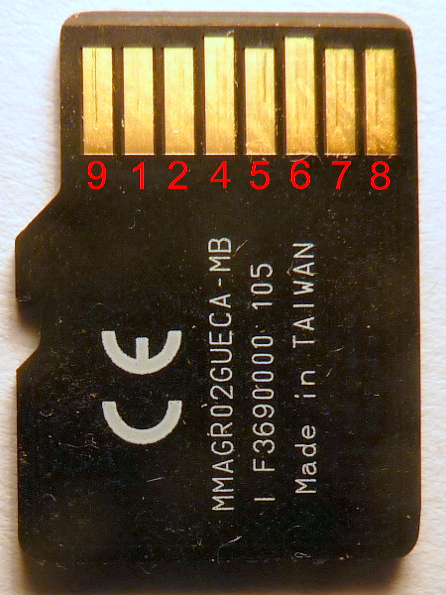
Circuit Diagram: SD and Micro SD Card pins with description and function. Secure Digital is what SD means, it is a flash based removable memory card. Micro SD Card is a type of Removable small flash memory card format, and has a dimensions of 11mm x 15mm and 1mm thick. Micro SD is short hand for Micro-Secure Digital.
Arduino SD Card Module How to Read/Write Data StepbyStep Tutorial
The Pine Ridge Reservation in southwestern South Dakota is massive. At more than 5,400 square miles, it's one of the largest reservations in the U.S. Add in a limited number of officers and a.
Add an SD card slot to a WRT54G v2 « Your Warranty Is
SI - this is the S erial I n / M icrocontroller O ut S erial I n pin, for data sent from your processor to the SD card. Its an input to the chip and can use 3V logic only. CS - this is the C hip S elect pin, drop it low to start an SPI transaction. Its an input to the chip and can use 3V logic only. Pull ups are provided on all SPI logic pins.
MicroSD Pinout A Stepbystep Guide
Arduino IDE ( online or offline ). Formatted SD Card * The boards/shields that have an SD card slot are listed below: MKR Zero MKR IoT Carrier MKR MEM Shield MKR SD Proto Shield MKR ENV Shield MKR Ethernet Shield Arduino Education Shield Circuit Here is an example of how to insert an SD card into the MKR Zero board.
Understanding the Labels on Memory Cards Integral Memory
Do the wiring between the Micro SD Card module and ESP32 as the above wiring diagram. Connect ESP32 to PC via USB cable. Open Arduino IDE, select the right board and port. Open Serial On Arduino IDE. Copy the above code and paste it to Arduino IDE. Click Upload button on Arduino IDE to upload code to ESP32. The result on Serial Monitor for the.
SD Card Interface FAQs and Answers Delkin Devices
Pin Configuration MicroSD Card Features and Specifications Operating Voltage: 2.7V to 3.3V Capacity: 4GB, 8GB, 16GB, 32GB etc.. File System: SD/SDHC/SDXC Storage System: FAT12 and FAT16 Transfer Speed: 95 Megabytes per second (typically) Speed Class: Class 2 to Class 10 Form Factor: 11mm × 15mm × 1mm Where to use an SD card
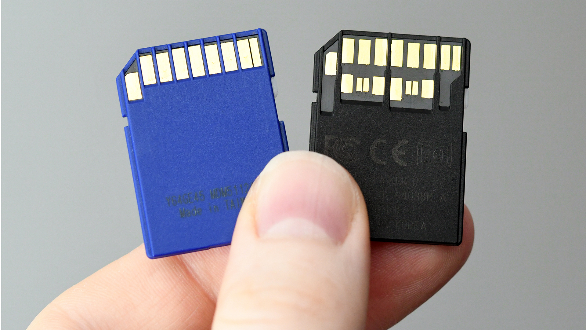
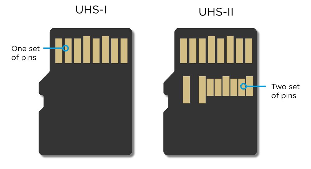
Why do some SD cards have two rows of pins? Digital Camera World
The Pine Ridge Reservation spans more than three million acres, larger than Rhode Island and Delaware combined, and features a variety of landscapes ranging from grasslands and rolling hills to.

Sd Card Pinout To Usb Webcas Org My XXX Hot Girl
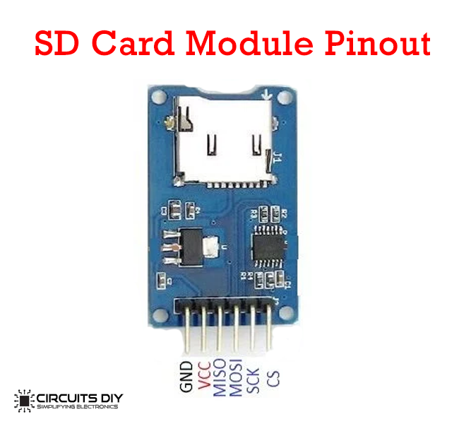
The microSD card module is simple to connect. There are six pins on it: VCC pin provides power to the module and should be connected to the Arduino's 5V pin. GND is a ground pin. MISO (Master In Slave Out) is the SPI output from the microSD card module. MOSI (Master Out Slave In) is the SPI input to the microSD card module.

Pin on Electronic components
Would be nice to have some schematics and firmware for this board. can confirm, they are quite nice & straightforward to install. works exactly how you'd expect them to. none of the jank which comes with the other generic adapters. One of a member (here or r/moddedipod) had been stress testing these on their ipod.
How to Read and Write Data in Arduino SD Card
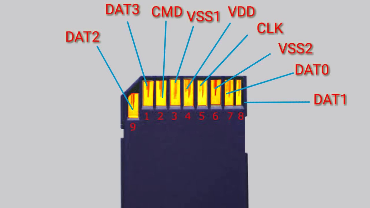
DAT1 DAT2 The very small microSD cards have only 8 pins. On those there is only one VSS pin. To these, the SD card slot adds three pins: Card Detect (CD) Common Switch Write Protect (WP) Note: only eight of the pins are used in this project. Power Pins Pins VSS1, VSS2 and VCC relate to power supply.
Read and write on a SD card with Arduino • AranaCorp
Micro SD Card Module Pinout. The Micro SD Card module has 6 pins; those are GND, VCC, MISO, MOSI, SCK, and CS. All the pins of this sensor module are digital, except VCC and Ground. The Pinout of a Micro SD Card Module is shown below: GND is the ground pin of the micro sd card module and it should be connected to the ground pin of the Arduino.
Arduino nano pinout sd card brokerspikol
The pin configuration of the micro SD card module is shown below. This module includes six pins to provide power & interacting through the controller. So in the following, each type of pin is described with its functionality. Micro SD Card Pin Configuration GND pin connects to the ground terminal VCC is a voltage input pin
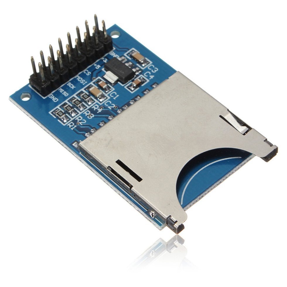
Micro SD Card Socket Push In Pull Out [6174] Sunrom Electronics
Secure Digital (SD) is a flash memory memory card format used in portable devices, including digital cameras and handheld computers. SD cards are based on the older Multi Media Card (MMC) format, but most are physically slightly thicker than MMC cards. They also boast higher data transfer rates. DRM features are available but are little-used.