12v Solenoid Wiring Diagram
Step 1: Gather the Necessary Tools and Materials Before you start wiring the Ford solenoid, make sure you have all the necessary tools and materials. These may include a wrench, wire strippers, electrical tape, and a wiring diagram specific to your Ford vehicle's model and year.
Solenoid Valve Wiring Schematic
Understanding the Starter Solenoid Wiring Diagram Starter Solenoid Wiring Diagram ples of electromagnetism in its work. When the ignition key is turned on, it sends an electrical signal to the solenoid, which then engages the starter motor and cranks the engine.
[1+] How To Wire A 12v Solenoid, Small PushPull Solenoid 12VDC ID 412 7.50 Adafruit
122 Share Save 77K views 12 years ago Automotive Diagnostic & Wiring Diagram Solenoid Wiring Diagram Amazon Printed Books.more.more Rating No mature content Solenoid Wiring.
4 Pole Starter Solenoid Wiring Diagram Manual EBooks 4 Pole Starter Solenoid Wiring Diagram
Starter Relay (Solenoid) 4 pole: How it works and an inside viewPlease Subscribe: https://www.youtube.com/channel/UCPHlB4ypxoILoDy7ihM3U5A/?sub_confirmation=.

Boss Plow Solenoid Wiring Diagram Naturemed
In this video I show how to wire a starter relay, starter solenoid, and neutral safety switch on an engine. I also explain how to bypass the solenoid if needed. This style starter circuit can.
Wiring Diagrams Solenoid Wiring Diagram Cadician's Blog
How to Wire a Starter (With Example Diagrams) - In The Garage with CarParts.com Learn how the starter and the rest of the starting system work in this comprehensive guide complete with wiring diagrams. Read more.
4 Pole Solenoid Wiring Diagram Cadician's Blog
Procedure on how to wire the electrical components in a solonoid valve, brought to you by http://stcvalve.us/CAUTION: Do not energize the coil before it is a.
3 Pole Starter Solenoid Wiring Diagram Database Wiring Diagram Sample
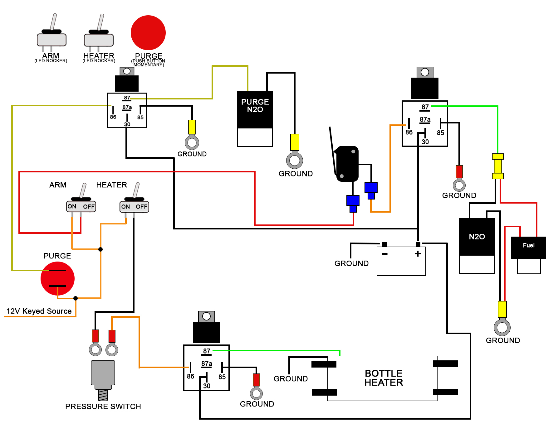
Wiring Diagrams. The first step in wiring a 4 Pole Continuous Duty Solenoid is to familiarize yourself with the wiring diagram. A wiring diagram is a graphical representation of the electrical system that shows the connection between the components. This diagram will help you identify the wires, components and their locations.
4 Pole Solenoid Wiring Diagram Wiring Diagram 4 Pole Solenoid Wiring Diagram Cadician's Blog
The wiring diagram of a 4 pole solenoid typically includes labels for each coil, as well as symbols to represent connections to the battery, ground, and other circuits. By following this diagram, you can identify the input and output connections for each coil and ensure that they are properly connected.

12 Volt Solenoid Relay Wiring Diagram
Each wire has a specific role and needs to be connected to the right terminal. If the connections are incorrect, the solenoid may not work as intended. It is important to refer to the wiring diagram provided by Briggs and Stratton to ensure proper wire connections. Another wiring issue that can occur is loose or corroded connections.
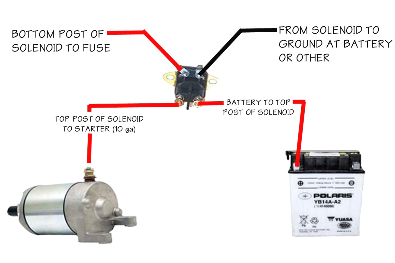
Polaris Sportsman 500 Solenoid Wiring Diagram
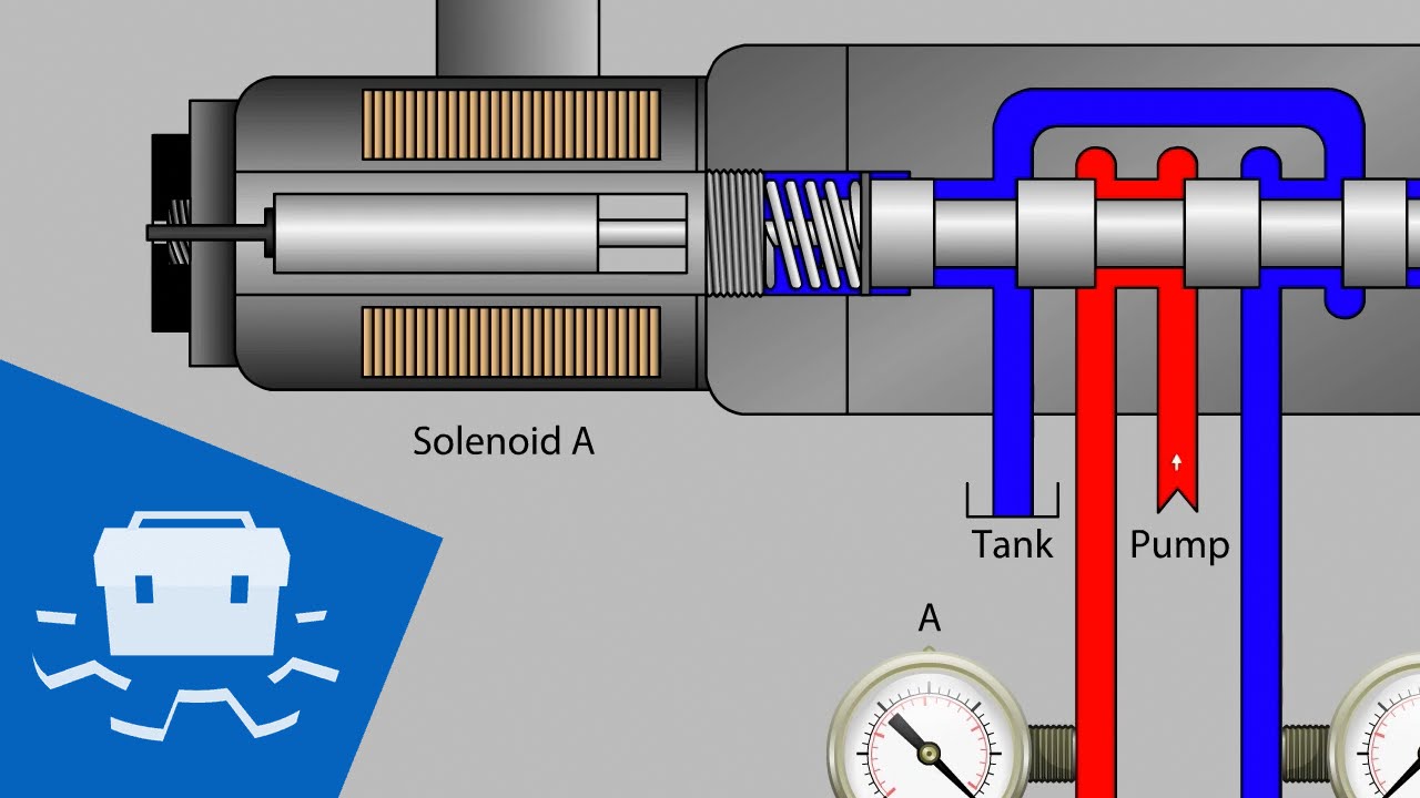
The wiring diagram of the solenoid valve is as below. Although the wiring of solenoid valve is simple, but poeple still encouter problems when wiring the solenoid valve to other devices. Here are some problems for your reference. 1. Is it that the solenoid valve on the pneumatic stop valve can be two-wired, three-wired or four-wired?

cole hersee solenoid 24059 wiring diagram
Pin No. Solenoid Control Wire Color Only 1Red 2Green 3White 4Black Pin No. Wire Color Control Function 1Red +12V 2Red Signal 3Black Signal 4Black Ground 4-Pin Pin No. Wire Color Control Function 1Red +12V 2Black Ground 3Tan Signal 4White Signal 11-Pin Pin No. Wire Color Control Function 1 Black/White PS Low Beam 2Black/Orange Ground 3 White.
Echlin Solenoid 36 Volt Wiring Diagram
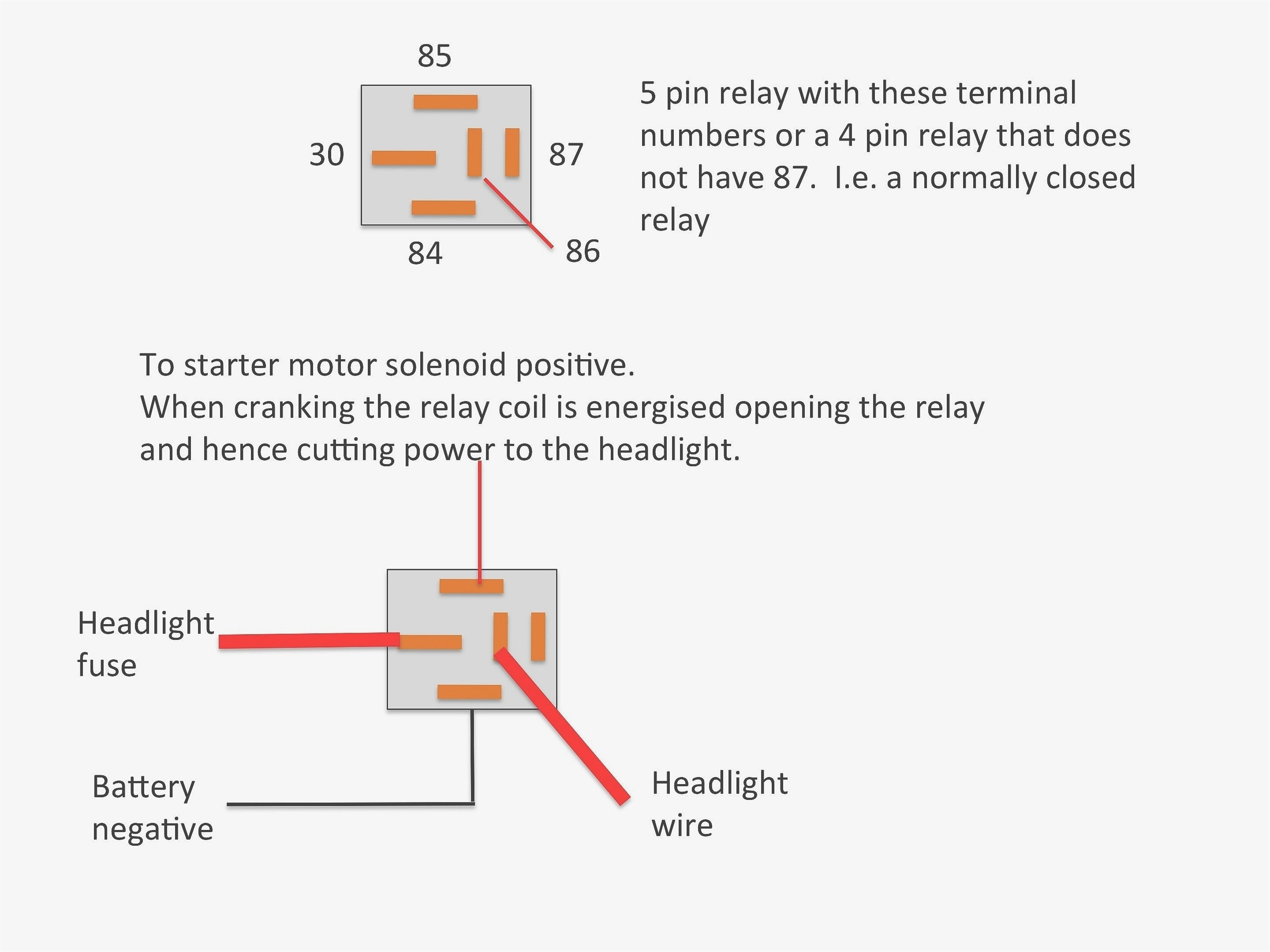
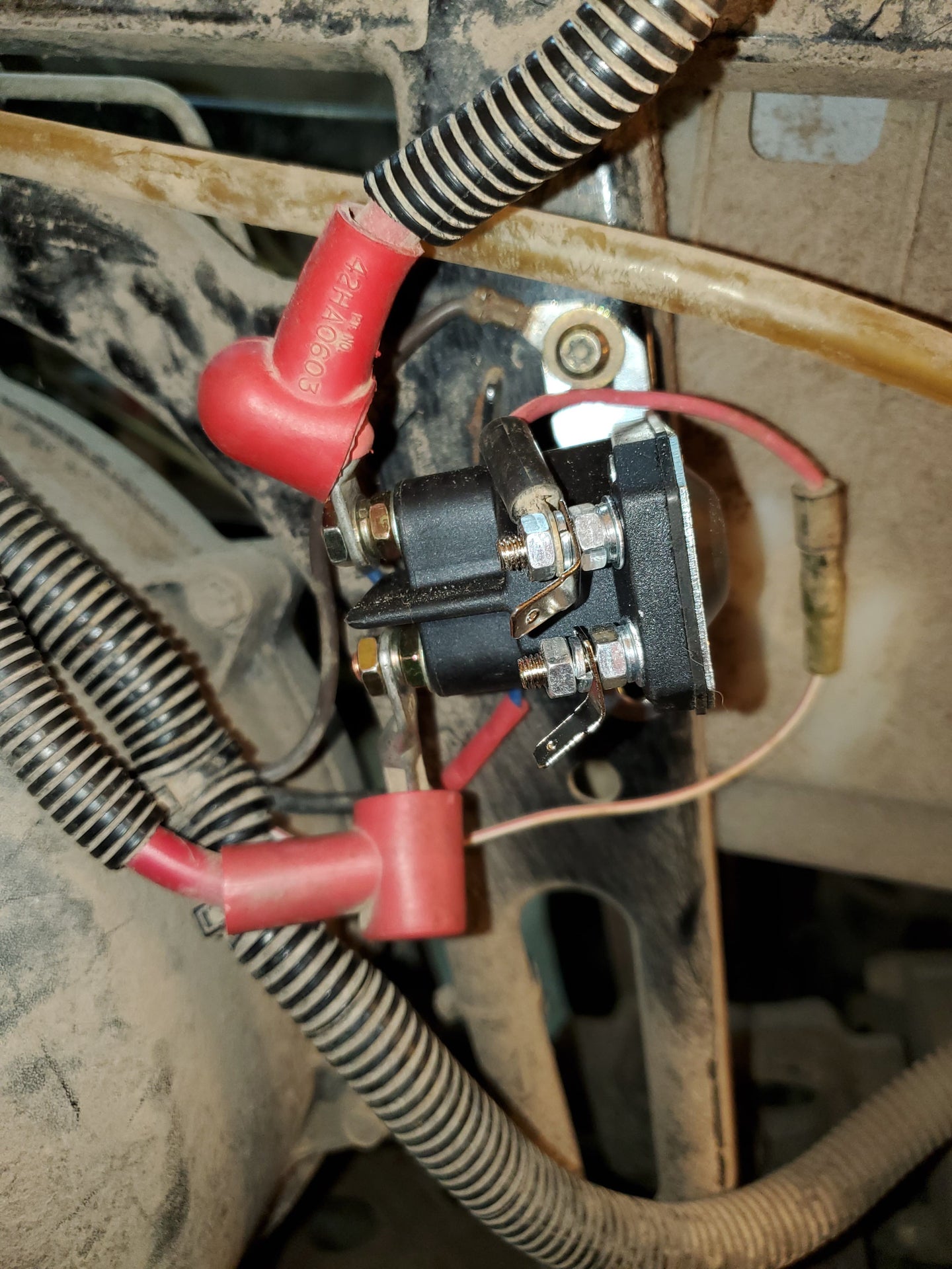
Wiring process of solenoids A starter solenoid usually has four terminals: two terminals are used for the high current circuit and the other two are the low current terminals of the solenoid, which are connected to the inner coil, and are the ones that trigger the high current device on the high power end.

Briggs And Stratton 11 Hp Ic Solenoid Wiring Diagram
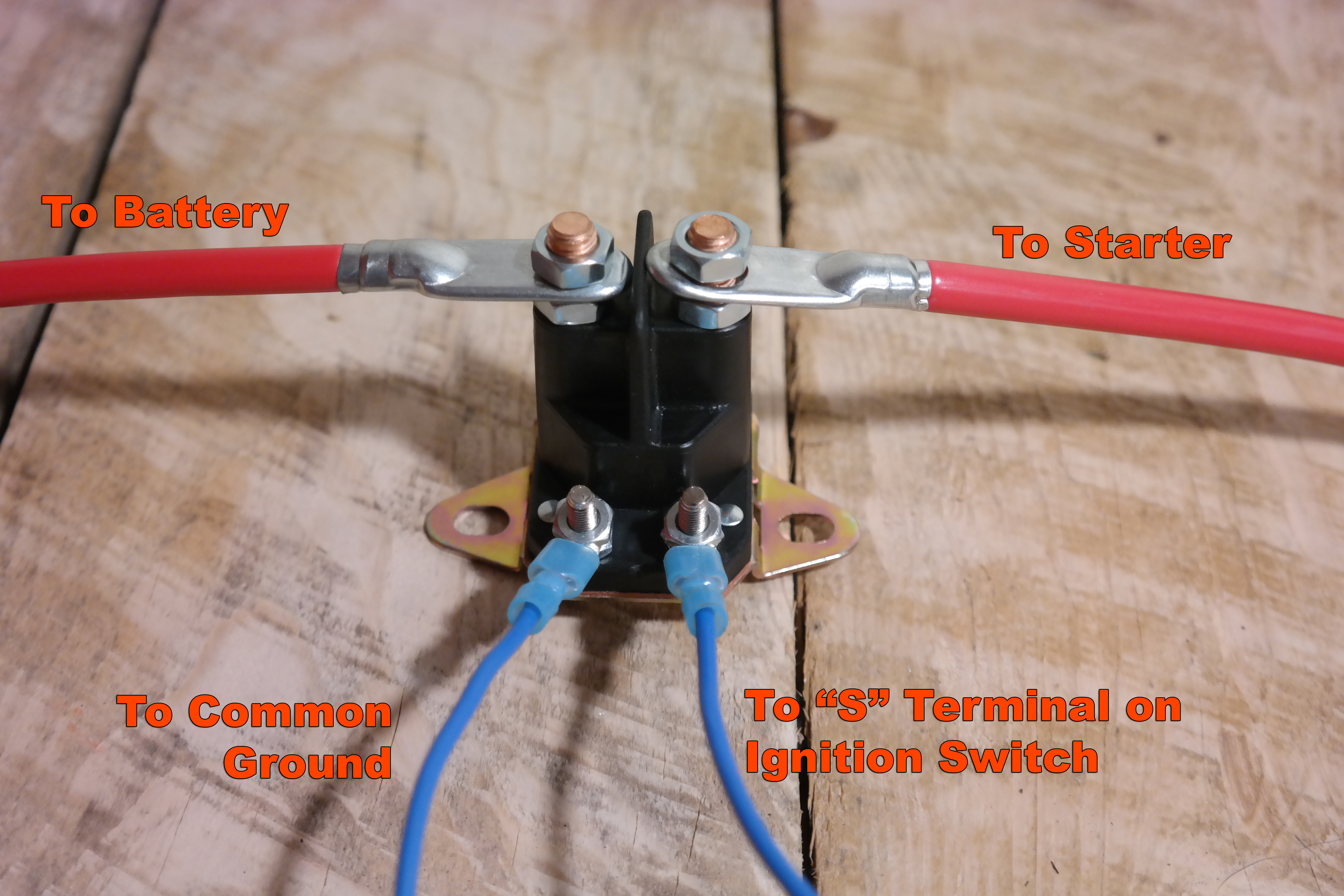
The externally switched (3-wire) solenoid is used in applications where an operator/driver manually turns a key switch that temporarily energizes the pull coil to pull in the plunger. The most common application is for start-stop control of engines in trucks and mobile equipment where moisture, dirt, dust, and high

️2 Wire Solenoid Wiring Diagram Free Download Goodimg.co
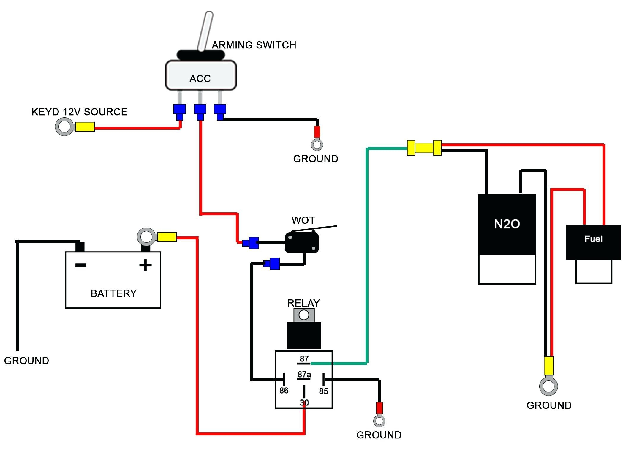
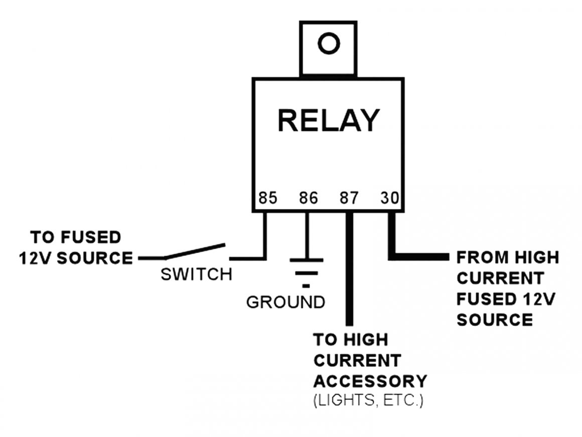
Once you have the wires and connectors chosen, you can begin the wiring process. To properly wire a 12v continuous duty solenoid, you will need to connect one end of the wire to the positive terminal on the solenoid and the other end to the negative terminal. It is also important to note that the wires should never be crossed or switched, as.

24059 Solenoid Wiring Diagram
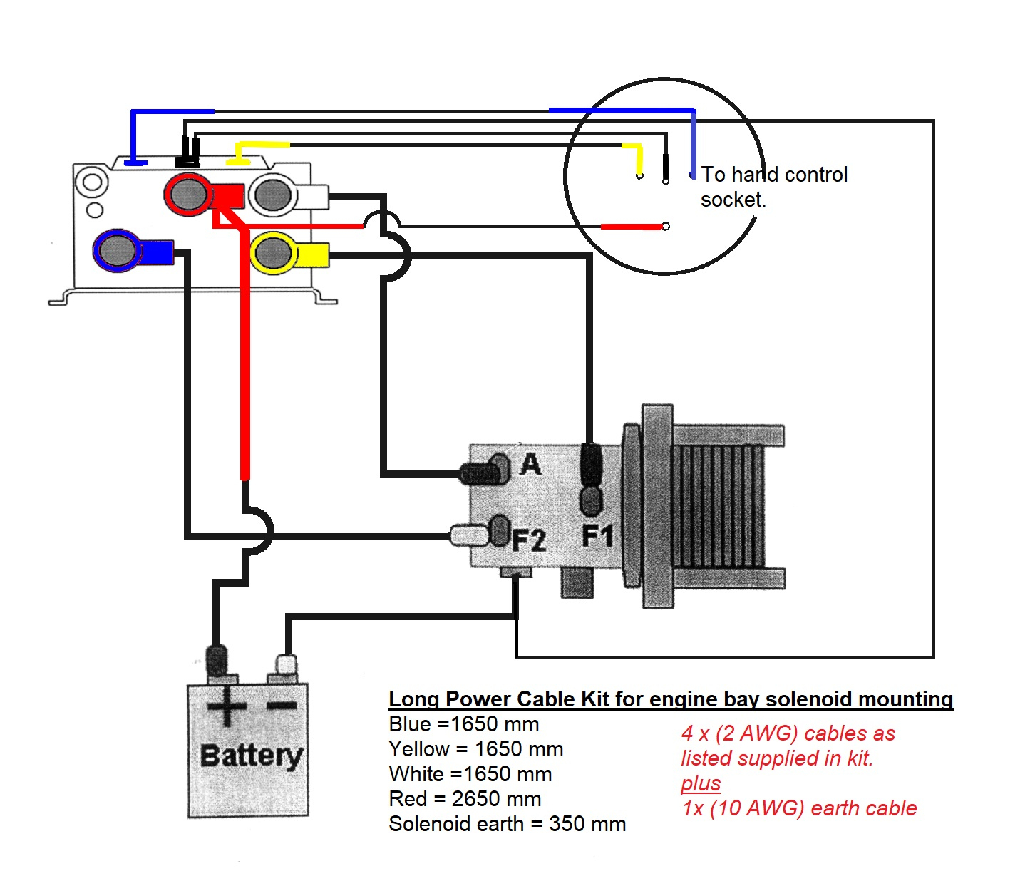
If you want to know the starter solenoid wiring diagram in simple words. This page explains very easily. On this powerful page, you will learn the solenoid wiring, especially the 3 pole wiring schematic for the starter solenoid in understandable language, so that you know what wires go to the starter solenoid.