Circuit Diagram Symbols Fuse Circuit Diagram
Fuse is one of the most common safety component for any equipment running on power. Almost all electrical/ electronic appliances and equipment utilize it some way or the other. This post will discuss what is a Fuse, why it is used, its symbols as per standards, features, various types, applications, advantages and disadvantages.
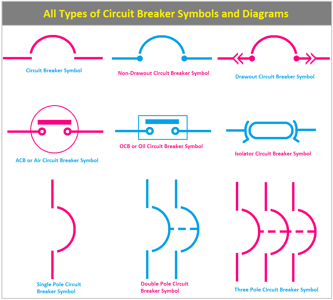
All Types of Circuit Breaker Symbols and Diagrams ETechnoG
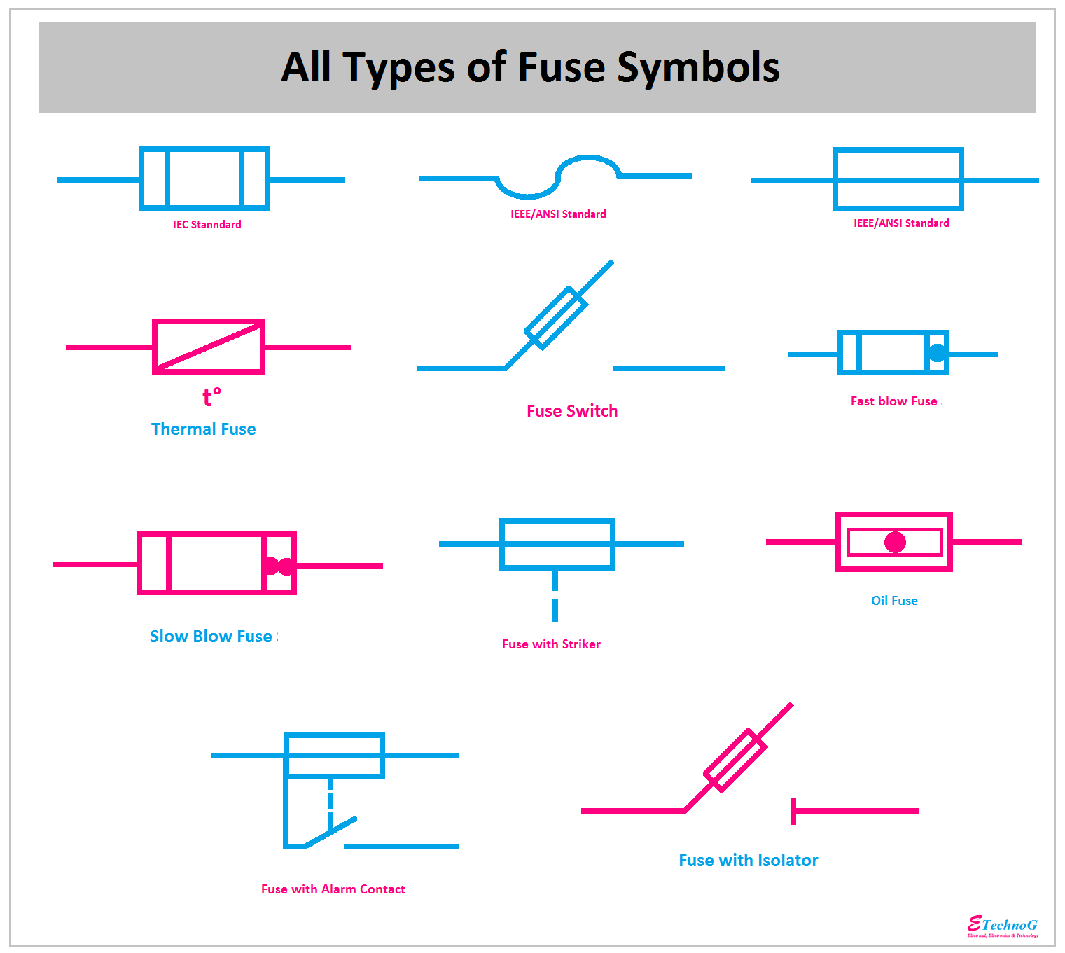
The symbol for a thermal fuse used in any electrical circuit diagram. A thermal fuse is a temperature sensitive switch. It operates on the temperature rather than the current unless the current is sufficient to increase the temperature above the threshold point. Fuse Switch This symbol represents a fused switch.

Schematic Symbol For Fuse
Fuse, general symbol Circuit breaker, general (IEEE/ANSI) 3-pole circuit breaker with magnetic-overload device in all 3 poles 11 31 51k Circuit Breaker 3P Fuse (IEEE/ANSI) Fuse with alarm contact Fuse-switch Disconnecting circuit breaker function 3-pole circuit breaker, drawout type Disconnecting circuit
Fuse Symbol
A fuse is an electrical safety device built around a conductive strip that is designed to melt and separate in the event of excessive current. Fuses are always connected in series with the component (s) to be protected from overcurrent, so that when the fuse blows (opens) it will open the entire circuit and stop current through the component (s).
Fuse Symbol
An electrical fuse is a safety device that operates to provide protection against the overflow of current in an electrical circuit. An important component of an electrical fuse is a metal wire or strip that melts when excess current flows through it. It helps to protect the device by stopping or interrupting the current.
What is Fuse? Types of Fuses and their Applications Electrical Academia
The standard IEEE/ANSI symbols for the fuse is as follows: However, the IEC fuse is slightly different: Types if Fuse Fuses can be divided into two major categories, AC fuses, and DC fuses. The below block diagram illustrates the different types of the fuse under each category. We will discuss each fuse in brief in our article. DC Fuses 1.
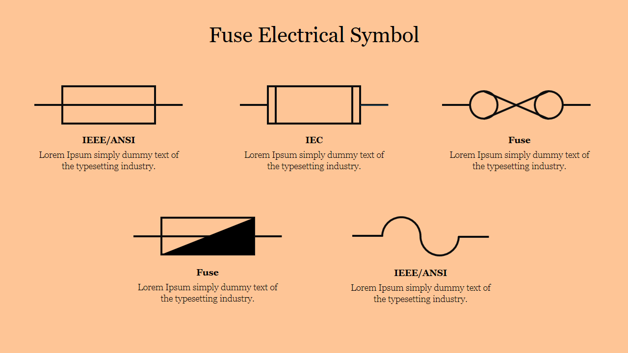
Fuse Electrical Symbol PowerPoint Template and Google Slides
The electrical schematic drawing symbol for a fuse is an S-shaped curve: Fuses are primarily rated, as one might expect, in the unit for current: amps.
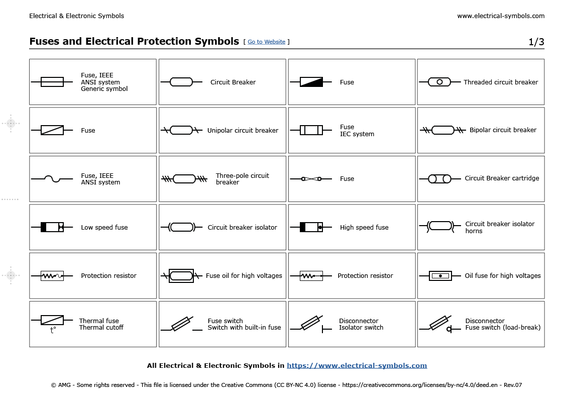
Símbolos Electrónicos Fuses and Electrical Protection Symbols
Fuse, Circuit Breaker and Electrical Protection Symbols Fact checked This article provides an overview of the most common symbols for fuses, circuit breakers, disconnect switches, and related protection devices in use today. Both ANSI/IEEE and IEC standards are referenced.

Pin on Electrical & Electronic Symbols
Electrical & Electronic Symbols www.electrical-symbols.com Fuses and Electrical Protection Symbols [ Go to Website ] 2/3 All Electrical & Electronic Symbols in https://www.electrical-symbols.com
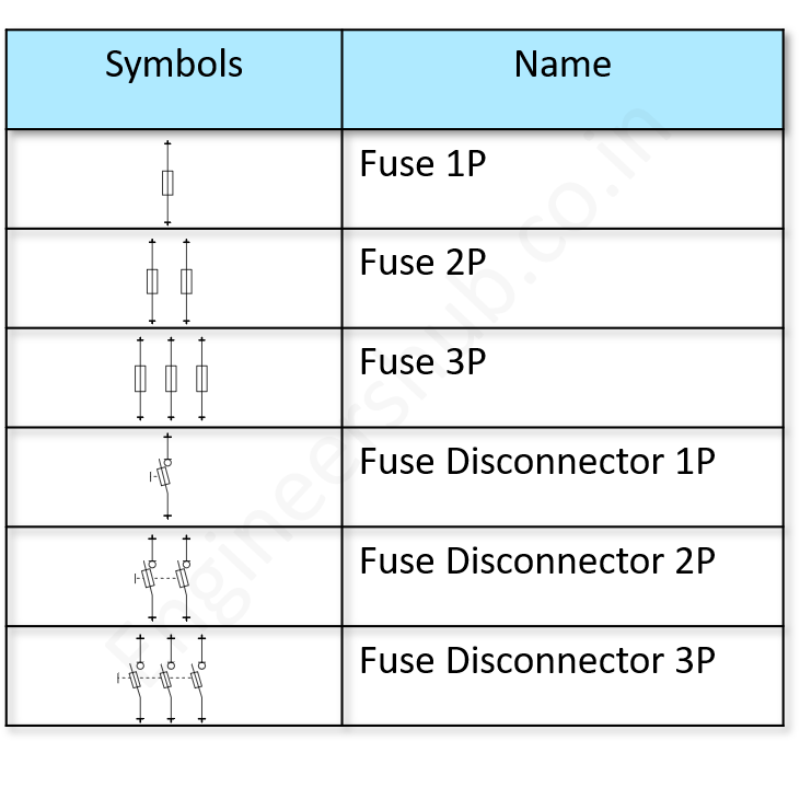
100+ Essential Electrical Symbols As Per IEC Standard Engineers Hub
The lines at the end of the diagonal appear to be used to indicate achieving an end state. Hence the other answer has a comment pointing out the difference between a PTC thermistor and PTC fuse symbol. The thermistor is not supposed to reach an end state of open circuit; the fuse does. Thus the PTC fuse symbol is, as already answered: or
Electrical Diagram Fuse Symbol Wiring Diagram
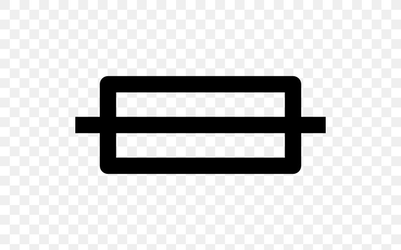
In any electrical circuit, fuses are represented by the symbols shown in the figure below. Fuse Symbol A fuse works by interrupting the flow of current in an electrical circuit when the current exceeds a predetermined level. The fuse consists of a metal wire or filament that is connected between two metal end caps.
Fuse Symbol
Fuses and Electrical Protection Symbols Fuses are devices containing a small piece of special wire that melts when the intensity of the current flowing through it for a certain period of time exceeds a set value, thus protecting the rest of the electrical circuit overloads. It may interest you.

Símbolos Electrónicos Fuses and electrical protection symbols
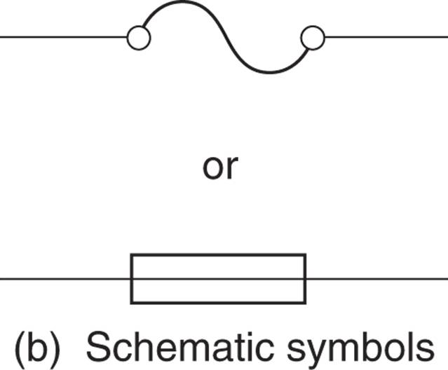
Fuse Symbols. Schematic symbols for a fuse are shown in the figure. Those at the right and second from right are most frequently used. The one in the center is approved by ANSI, IEC, and IEEE but is seldom seen. To the left of that is the fuse symbol understood by electrical contractors in architectural plans.

What Is The Symbol For A Circuit » Wiring Core
In electronics and electrical engineering, a fuse (from the French fuser, Italian fuso, "spindle") is a type of low resistance resistor that acts as a sacrificial device to provide overcurrent protection, of either the load or source circuit.
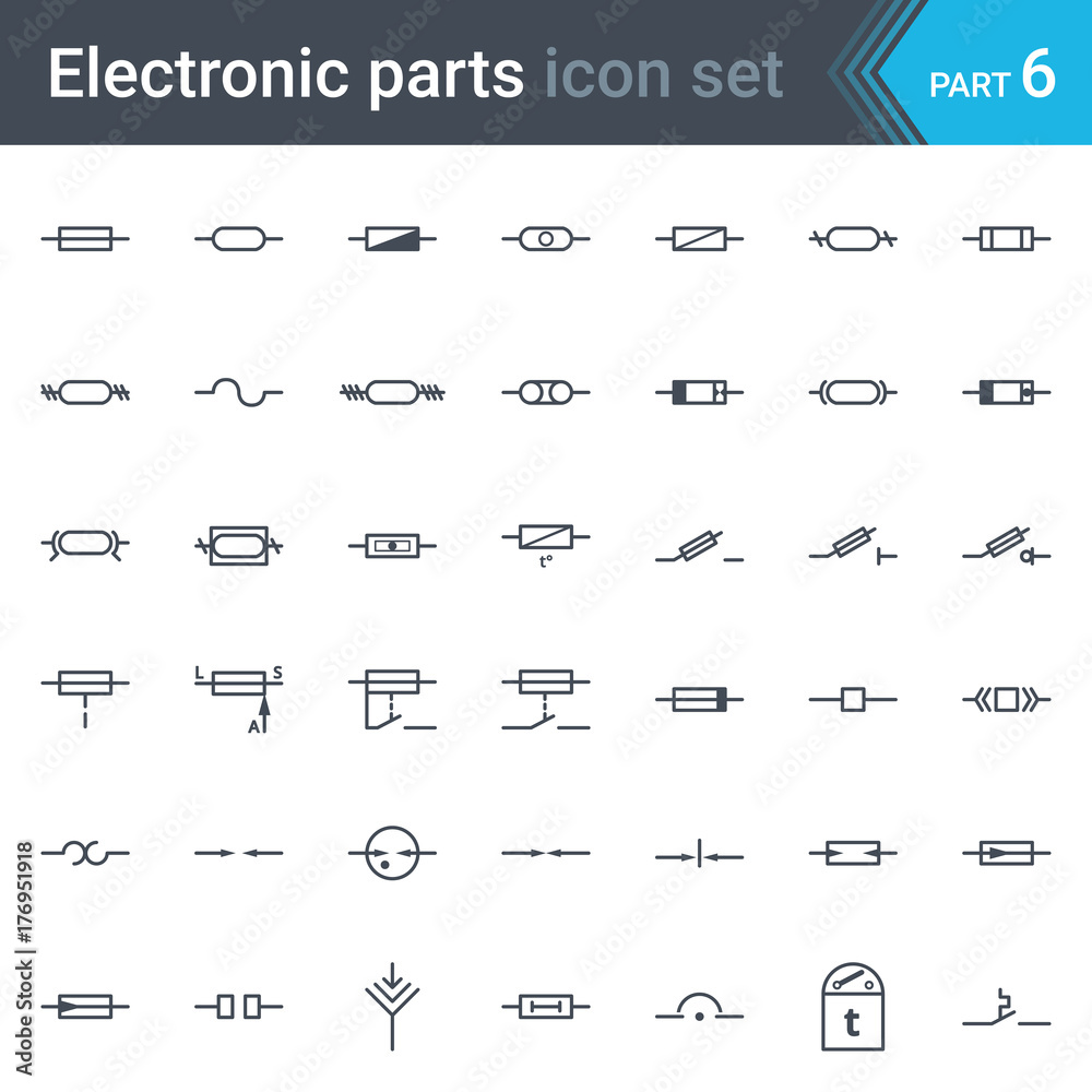
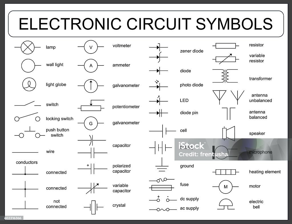
Complete vector set of electric and electronic circuit diagram symbols and elements fuses and
Cartridge fuse - a DC cartridge fuse is a low-cost safety device that is used in the protection of electrical circuits, machines, and appliances. They are cylindrical and have a contact point at either end of the fuse. Typically cartridge fuses are made of ceramic, glass, or porcelain materials. They come in a number of different sizes.
Circuit Diagrams Fuse Symbol
An Electrical Fuse is a safety device to limit the current in an electric circuit. Excess electric flow can cause damage without the fuse in place. Hence, the Electrical Fuse protects the circuit from damage while exceeding current or voltage fluctuations. It protects electrical appliances from overloads and short circuits.