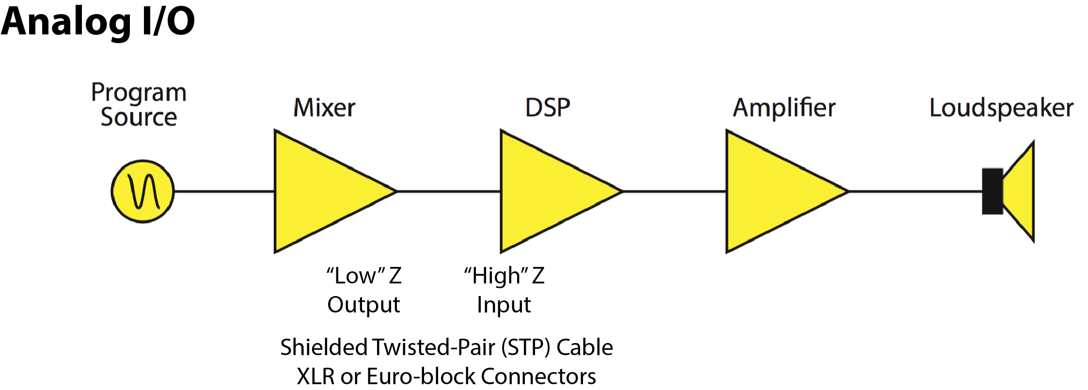
Analog Output The Bela Knowledge Base
Berikut ini kami akan menjelaskan pengetian digital input, digital output, analog input, analog output pada PLC beserta contoh perlatannya. Digital Input Pada PLC Digital input PLC adalah suatu sinyal masukan (informasi) yang hanya berupa dua kondisi, yaitu kondisi On atau Off dan biasa juga disimbolkan dengan kondisi 1 atau 0.
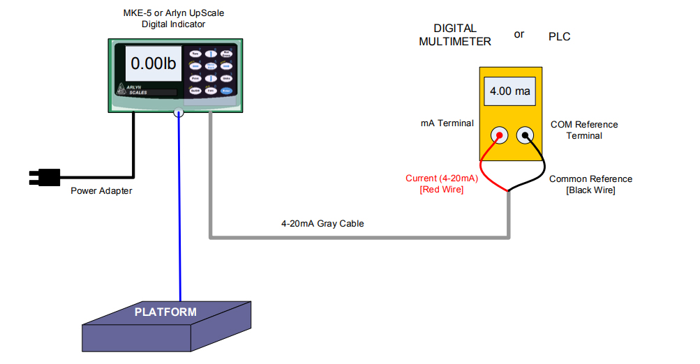
Analog Output 420mA/05VDC Wiring w/ Digital Indicator Arlyn Scales
Difference between DO and AO. A digital output is binary in nature, either it can be ON or it can be OFF. Either it can be 0V or it can be 24V based on the type of IO module used. Analog signal is a time-varying signal. It can be varying between 0-10V or 0-20mA based on the design. Hope the above content helped you understand the difference.

Penjelasan Apa Itu Digital I/O dan Analog I/O Wira Electrical Engineering Portal
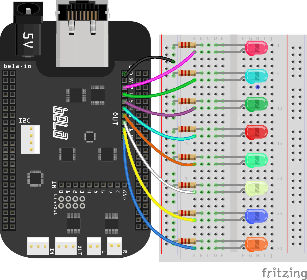
To control them, you use the analogWrite () command like so: 1. analogWrite(pin, duty); pin refers to the pin you're going to pulse. duty is a value from 0 - 255. 0 corresponds to 0 volts, and 255 corresponds to 5 volts. Every change of one point changes the pseudo-analog output voltage by 5/255, or 0.0196 volts.
22. analog inputs and outputs
A combined output succeeds in reducing the wiring cost, connector count, and increasing the versatility of the AO design. The possible outputs of the design include: 4-20 mA, 0-20 mA, 0-24 mA, 0-5 V, 0-10 V, +/-5 V, +/-10 V, as well as voltage over-ranges. Ask The Analog Experts WEBENCH® Design Center TI Precision Designs Library.

Programmable analog output circuit maximizes industrial system flexibility
Tools used in analog signal processing. A system's behavior can be mathematically modeled and is represented in the time domain as h(t) and in the frequency domain as H(s), where s is a complex number in the form of s=a+ib, or s=a+jb in electrical engineering terms (electrical engineers use "j" instead of "i" because current is represented by the variable i).
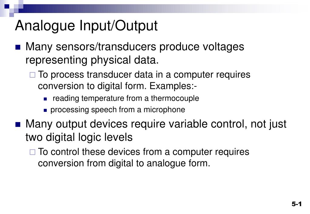
PPT Analogue Input/Output PowerPoint Presentation, free download ID3352152
There are a variety of discrete end devices and modules that can be used in a PLC system to send and receive on/off signals. These devices can be AC or DC and are available in different voltage ranges. 0-24VDC and 0-230VAC are two voltage ranges available, with 0 being the OFF signal and 24VDC or 230VAC being the ON signal.

How to Generate an Analog Output with Arduino UNO Geekering
The range of the analog output holding registers is 40001 to 49999, implying that there can be a maximum of 9999 registers. Although this is usually enough for most applications, there are cases where more registers would be beneficial. Registers 40001 to 49999 correspond to data addresses 0000 to 270E.

Pengertian Sinyal Analog Dan Digital Beserta Contohnya Kelas PLC
That's the main difference between discrete and analog I/O modules! Discrete signals are simply on or off, whereas analog signals vary. PLCs are responsible for collecting data from input signals and sending the information through output signals to control devices in order to perform specific functions. Depending on the application or device.
Understand the differences between analog and digital interfaces
The pins available for analog output are marked with the ~ symbol. On the Arduino Uno board, these are pins 3, 5, 6, 9, 10, and 11. The value must be between 0 and 255. This value controls how "on" the pin is. A value of 0 turns the pin off and a value of 255 means completely on. Any values in between 0 and 255 result in different levels of.

Basic Analog Circuit Tutorial and Overview Electronics and You
Baik digital dan analog I/O adalah hal mendasar untuk rangkaian dan aplikasi pemrosesan sinyal. Baik keduanya memiliki karakteristik, kelebihan, dan kekurangan masing-masing.. Apa itu Output Analog. Sama seperti input analog, output analog juga menghasilkan hasil berkelanjutan. Jika input berubah, maka output juga berubah hampir secara.
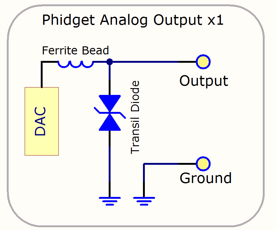
Analog Output Primer Phidgets Legacy Support
The function that you use to obtain the value of an analog signal is analogRead (pin). This function converts the value of the voltage on an analog input pin and returns a digital value from 0 to 1023, relative to the reference value. The default reference voltage is 5 V (for 5 V Arduino boards) or 3.3 V (for 3.3 V Arduino boards).

LucidIoT Network Analog Output Module
Read Analog Voltage using Arduino Uno. As ADC provide digital output which is proportional to analog value. To know what is input analog value, we need to convert this digital value back to analog value through program. To convert this digital value to analog input voltage, Aout = digital value * (Vref/2^n - 1)

Arduino Tutorial 13 [Analog input ] (Bahasa Malaysia) YouTube
Adigital-to-analogconverterproducesan analog output A that is proportional to the digital input D: A=aD, (4.1) 4S. 46 Basic Principles of Digital-to-AnalogConversion Chap. 4 where ex is a proportionality factor. Since D is a dimensionless quantity, ex sets both the dimension and the full-scalerange of A. For example, if ex is a
World Analog Inputs and Outputs
Analog input - AI. Analog input (AI) is a continuous time-varying input signal to the PLC/DCS. Whenever a system or device takes an input signal in analog format then it is known as Analog input - AI. In most of the standard automation systems, the Analog signal becomes generally continuous time-varying voltage and current signal having the range of values (0-10V), and (4-20mA) respectively.
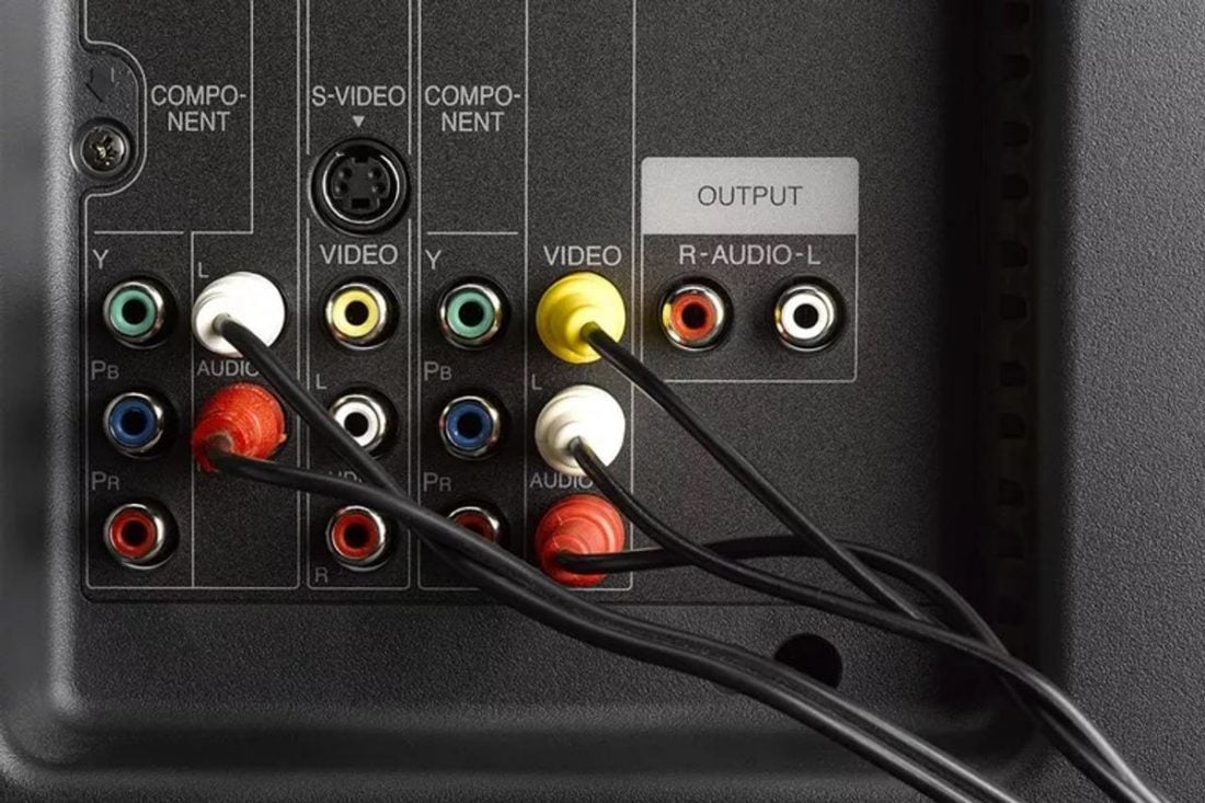
Ultimate Guide to Audio Output Headphonesty
A growing trend in the industrial application space is for analog output modules to provide both voltage and current outputs on a single terminal block. This saves manufacturers some of the costs associated with expensive connectors and cabling. Additionally, this gives a single analog output module the flexibility to serve in virtually any.

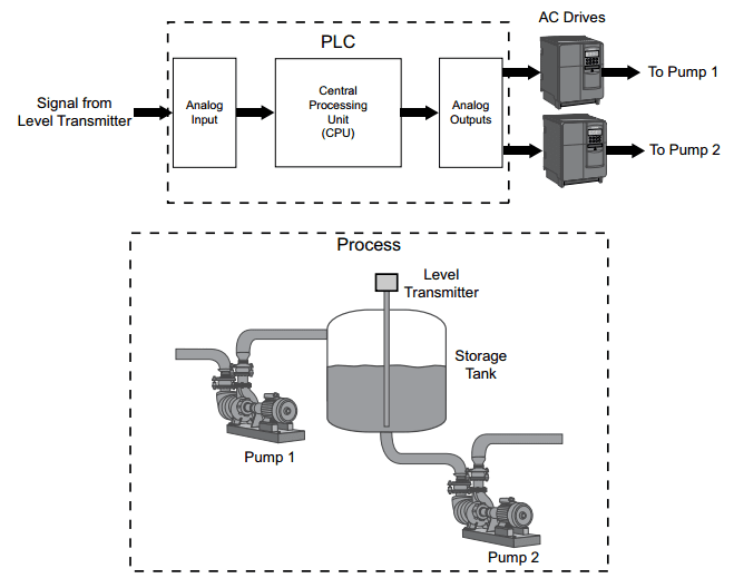
Analog Output Module Wiring With 2, 3, and 4 Wire Devices Technical Articles
An output module controls (turns on/off, ramps up/down, etc.) devices such as relays, motor starters, lights, gauges, etc. Discrete/digital I/O is either on or off (think light switch on or off). Analog I/O can be on or off or in between (think light switch dimmer). The inputs tell the PLC what to do with the outputs (depending on how you've.